
Description
🌐 Product Overview
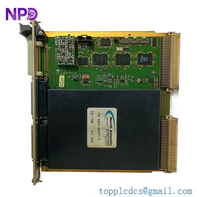
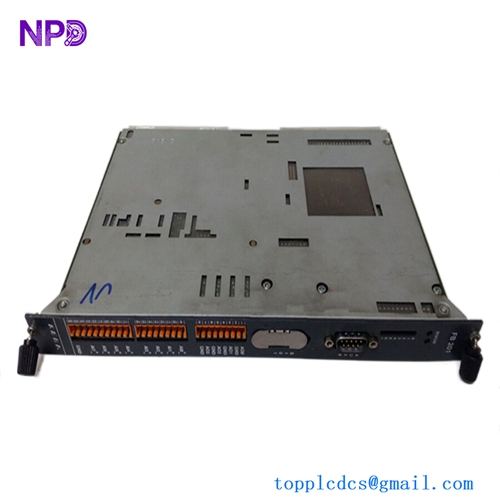
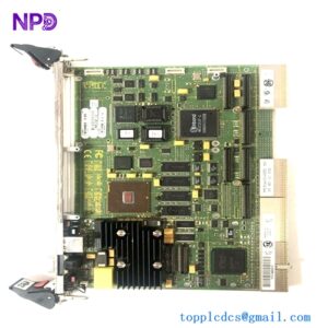
The Nabco MC-206-01 is a specialized, industrial-grade microcomputer control printed circuit board (PCB) card designed primarily for automated transit systems, pneumatic door systems, and heavy-duty commercial door operators. Engineered with advanced processing logic and highly stable timing circuits, this control board coordinates multi-stage sensor signals, safety mats, and motor encoders. It ensures smooth, reliable, and fail-safe door actuation sequences within high-traffic public infrastructure and demanding industrial facilities.
⚙️ Technical Specifications
- Series: MC Control Board Series
- Dimensions: 180mm x 140mm x 28mm
- Weight: 0.45 kg
- Origin: Japan
- Logic Processor: Integrated 8-bit/16-bit industrial microcontroller
- Input Signals: 12-24V DC digital inputs for radar sensors, photocells, and safety switches
- Output Drive: Relay or solid-state outputs rated up to 5A for motor control loops
- Main Operating Power: 24V AC/DC operational threshold
🚀 Application Fields
- Platform Screen Doors (PSD): Manages synchronized opening and closing sequences for safety doors in subway and rapid transit rail stations.
- Pneumatic Door Actuators: Controls industrial pneumatic and hydraulic access doors in food processing and manufacturing facilities.
- Commercial Automatic Entrances: Heavy-duty slide, swing, and revolving doors inside airports, hospitals, and shopping complexes.
- Logistics & Warehousing: High-speed rolling shutter door automation tied into localized security networks.
📖 Product Instructions
- Card Installation: Ensure the main control box housing is unpowered. Slide the MC-206-01 PCB card onto its designated chassis guide rails or mount it onto non-conductive standoffs, securing it with anti-vibration screws.
- Terminal Wiring: Follow the standardized system wiring diagram to connect sensor inputs, limit switches, and motor drive lines to the card’s pluggable terminal blocks. Maintain separate routing for signal wires and high-amperage power lines.
- Parameter Tuning: Adjust the onboard potentiometers or set the internal DIP switch matrix to program specific holding times, deceleration zones, and motor braking forces.
✅ Initial Startup Checklist
- Verify that the power supply output matches the voltage requirements specified on the card (24V AC/DC).
- Check that the edge-connector or pluggable terminal blocks are pushed completely flat into their sockets and locked.
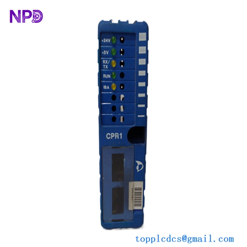
- Power up the unit and observe the onboard status LEDs; the primary “Power” or “Run” LED should illuminate steady without error patterns.
- Perform a low-speed manual test cycle to verify that the opening and closing limit switches trigger correctly on the board.

🛠️ Maintenance & Care
- Debris Removal: Inspect the PCB card every six months for traces of conductive dust, moisture, or insects. Clean gently using an anti-static brush and a specialized electronic contact cleaner.
- Terminal Integrity Check: Check all screw terminals and plug headers during routine facility maintenance to ensure building vibrations haven’t loosened wire connections.
- Solder Joint Inspection: Periodically review the board for signs of component overheating, swelling capacitors, or dry solder joints around high-load output relays.
⚠️ Safety Precautions
- Static Hazard: Always wear a grounded electrostatic discharge (ESD) wrist strap when extracting, adjusting, or inserting the PCB card to avoid damaging internal microprocessors.
- Isolate Power First: Do not hot-plug the terminal connectors or the main card assembly while the power distribution system is live.
- Obstruction Testing: Always ensure the automatic door’s secondary safety sensors (e.g., photo-eye or safety reverse edge) are fully functional before leaving the board in unattended automatic mode.
🔍 Troubleshooting & FAQ
- Q: The door does not open, and a specific error LED on the card is flashing continuously.
- A: A flashing indicator usually signals a safety circuit break or a blocked sensor loop. Check if the safety beam photo-eye is misaligned, dirty, or if an emergency stop circuit is open.
- Q: The motor struggles to move or shuts off mid-cycle before reaching the limit switch.
- A: This may indicate an overcurrent trip caused by high mechanical friction in the door track, or an incorrectly set current-limit potentiometer on the MC-206-01. Inspect the track mechanics before adjusting board sensitivity.
- Q: Can this board be directly dropped into older Nabco MC-series systems without modifications?
- A: The MC-206-01 maintains backward compatibility with specific older configurations, but pin definitions and DIP switch layouts may vary. Always cross-reference your original system wiring blueprint before switching cards.