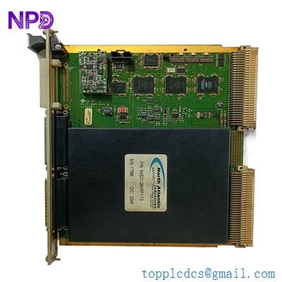
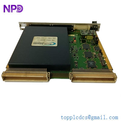
Description
- Model: NAI 64SD1-08KRF1-13
- Brand: North Atlantic Industries (NAI)
- Series: 64SD1 / VME Measurement Series
- Core Function: High-precision conversion of Synchro/Resolver signals to digital data
- Product Type: VME Synchro/Resolver-to-Digital (S/D) Measurement Board
- Key Specs: 16-bit resolution, 16 S/D converter channels, Type II servo loop processing
NAI 64SD1-08KRF1-13
Key Technical Specifications
- Architecture: VMEbus 6U Form Factor
- Channels: 16 independent S/D (Synchro/Resolver-to-Digital) channels
- Resolution: 16-bit (high accuracy for position/velocity tracking)
- Accuracy: ±1 arc-minute (standard for single-speed inputs)
- Tracking Rate: Up to 833 RPS (based on bandwidth configuration)
- Phase Shift: Automatic compensation up to ±60°
- Signal Inputs: 2 V to 28 V L-L (Line-to-Line)
- Reference Input: 2 V to 115 Vrms (47 Hz to 1 kHz range)
- Self-Test: Background Built-In-Test (BIT) with wrap-around capability
- Power: +5 V DC @ 1 A (typical backplane draw)
- Velocity Output: 16-bit digital velocity data with 0.1% linearity
- I/O Format: P2 and front panel I/O options (verify specific revision)
Installation & Configuration Guide
Phase 1: Pre-Installation (Estimated time: 15 minutes) ⚠️ Safety First:
- Turn off the VME chassis power. Working on a “hot” backplane can damage the high-density S/D converter chips.
- Confirm the Reference Voltage (Vrms) and Frequency (Hz) of your Synchros. The 64SD1-08KRF1-13 is sensitive to overvoltage on reference inputs.
- Use a grounded wrist strap. NAI boards utilize high-precision analog-to-digital circuitry that is extremely susceptible to ESD.
Phase 2: Removal (Estimated time: 5 minutes)
- Unplug Front Connectors: If your version uses front-panel I/O, carefully label each connector. These carry high-frequency AC signals that are prone to cross-talk if not shielded properly.
- Release Handles: Pull the top and bottom VME ejector handles outward to unseat the 96-pin DIN connectors from the backplane.
- Inspect the Slot: Check the P1 and P2 slots for dust or bent pins. S/D signals are low-voltage AC; a poor connection here will cause “jitter” in your position readings.
Phase 3: Installation (Estimated time: 20 minutes)
- Set Jumpers/DIPs: The 64SD1 uses onboard jumpers to define the board address and VME interrupt levels. Match these exactly to your old board’s configuration.
- Slide and Seat: Slide the board into the rails. Ensure the P1/P2 connectors are aligned. Push the handles in until they lock.
- Wire Termination: If using P2 I/O, ensure the transition card is properly seated. If using front-panel wiring, ensure the shield is grounded at the module faceplate.
- Configuration (Important): NAI modules often require software-based initialization for bandwidth and signal type (Synchro vs. Resolver). Verify your boot-up scripts.
Phase 4: Power-On & Testing (Estimated time: 30 minutes)
- Power up the VME rack.
- Check Diagnostic LEDs: NAI boards usually have a “Fail” or “Status” LED. A green light indicates the Built-In-Test (BIT) passed.
- Reference Verification: Use an oscilloscope to verify the excitation signal is present at the module inputs.
- Signal Sweep: Rotate the shaft of the connected Synchro/Resolver and verify the digital count increments smoothly in your control software.
Customer Cases & Industry Applications
Case 1: Aerospace Test Stand Maintenance An aerospace contractor in the UK was maintaining a legacy flight simulator rack. The original NAI 64SD1 module failed, causing the “Heading” and “Pitch” displays to jitter uncontrollably. The lead time for a new custom module from the OEM was over 20 weeks. We delivered a New Surplus 64SD1-08KRF1-13 in 5 days. After copying the jumper settings, the simulator was back in service, allowing pilot training to continue without interruption.
Case 2: Marine Radar Positioning System A commercial shipping vessel’s radar pedestal used a North Atlantic S/D converter to report the antenna’s precise angular position. When the module failed due to years of vibration and salt-air exposure, the radar could no longer track targets accurately. We provided a certified surplus replacement. Because the 64SD1 is a “drop-in” VME replacement, the ship’s electrician was able to swap the board at the next port, avoiding an expensive stay in dry-dock.
NAI 64SD1-08KRF1-13
Frequently Asked Questions (FAQ)
Q: Can this module handle both Synchros and Resolvers? A: Yes. The 64SD1 series is highly programmable. However, in my experience, the wiring and the internal configuration must be set specifically for either a 3-wire Synchro or a 4-wire Resolver. Check your system software to see if it sends the configuration command upon boot.
Q: What does the “-13” at the end of the part number mean? A: This usually denotes a specific hardware revision or a factory-set configuration (such as specific input voltage or temperature range). While many 64SD1 boards are versatile, it is always safest to match the full suffix to ensure the “KRF” configuration (likely relating to the excitation or frequency range) matches your existing logic.
Q: Why is my position data “jumping” or showing 0.00? A: This is often a “Reference Loss” error. If the module does not detect the AC excitation signal (Ref High/Ref Low), the S/D converters cannot calculate the angle. Check your external reference supply and the diagnostic LEDs on the board.
Q: Does this board support “Two-Speed” Synchro inputs? A: Yes, the 64SD1 architecture supports combining two channels for two-speed (e.g., 1:36 or 1:72) accuracy. This must be enabled in your control software project.
Q: How do I verify the accuracy of the 16-bit output? A: We recommend using a Synchro/Resolver Simulator (like an NAI 5300 or similar) to feed a known angle into the board. If the digital output from the 64SD1 matches the simulator within ±0.02°, the board is performing within its high-accuracy specifications.
I’m always open to corrections if I get something wrong; the best way to handle that is to just tell me what I missed or what I need to know! You can also always turn off the use of this personal context in your settings.