
Description
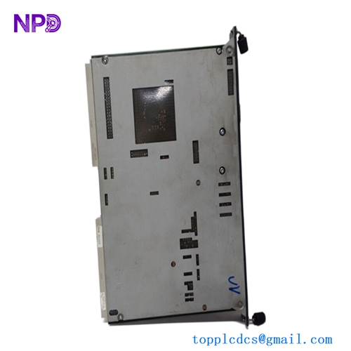
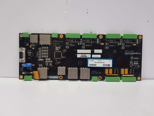
The OCEANEERING 0300563-1 (often identified by assembly number 0300563) is a specialized Ground Fault Isolation PCB card. Designed for the harsh environments of subsea and maritime control systems, this module provides critical protection by isolating electrical circuits when a ground fault is detected. It prevents fault propagation, ensuring the overall integrity of sensitive remote control and monitoring equipment in subsea or offshore hydraulic/electronic control panels.
⚙️ Technical Specifications
- Dimensions: 160 mm x 100 mm x 25 mm
- Weight: 0.3 kg
- Country of Origin: United States / International (Oceaneering standard)
- Supply Voltage: 24V DC / Common Control Voltages
- Operating Temperature: -20°C to +60°C (Subsea-rated enclosure required)
- Protection Class: Requires housing in a pressure-compensated or sealed dry-mate enclosure
- Fault Response: Automatic isolation upon detection of leakage current to ground
🏗️ Application Areas
- Subsea Production Control Systems (SPCS)
- Offshore Drilling Rig Control Panels
- Remotely Operated Vehicle (ROV) Surface Control Units
- Marine Hydraulic/Electric Control Interfaces
- Safety-Critical Power Distribution
📖 Product Usage Instructions
This PCB must be installed in an environment shielded from subsea moisture or extreme pressure, typically within a dry-mate electronics canister. Ensure the PCB is securely mounted using non-conductive standoffs. When wiring, maintain a strict separation between power-carrying conductors and sensitive signal lines. Ground fault sensing leads must be routed directly to the system’s isolated common return to ensure accurate fault detection.
🌐 Communication Configuration Steps
- Status Signaling: The card typically provides a “Fault” or “Status” digital output (dry contact or transistor) to the main controller.
- Sensitivity Adjustment: If the module includes physical potentiometers or jumpers, configure them to match the system’s permissible leakage threshold (mA) according to the project’s safety specifications.
- Baud Rate: This module functions primarily as an analog/logic isolation hardware and does not require digital communication settings.
⚡ Power-Up Debugging Flow
- Verify the incoming supply voltage is within the specified 24V DC range.
- Ensure the “Ground Fault” test LED is inactive on startup.
- Apply power and check the module’s “Healthy/Status” LED for a steady green state.
- If a “Ground Fault” light is active, check the external cabling for insulation degradation or water ingress.
- Confirm the isolation relay output is in the “Closed” (Normal) position using a multimeter.
✅ Initial Run Checklist
- Perform a “Ground Fault Injection Test” to confirm the module triggers the isolation relay within the required safety timeframe.
- Verify the isolation resistance between the circuit positive/negative and the chassis ground.
- Document the baseline leakage current readings for future maintenance comparison.
- Check all screw terminal connections for tightness to prevent high-resistance contact points.
- Confirm that the fault-triggered alarm reaches the surface HMI or monitoring console.
❓ Frequently Asked Questions (Q&A)
Q: What happens when a ground fault is detected? A: The card detects a current leakage to the ground plane and triggers an internal isolation relay, disconnecting the faulted circuit to prevent further damage or complete system failure.
Q: Can this PCB be used in high-pressure subsea environments? A: No, this PCB is a surface-logic component. It must be housed within a pressure-compensated or atmosphere-controlled canister if deployed at depth.
Q: How do I identify if the board has tripped? A: There is typically an onboard LED indicator (Red) that illuminates when a fault is active. Additionally, the isolation relay will switch state, which can be verified at the output terminals.
Q: Are these modules repairable after a major fault? A: Due to the safety-critical nature of isolation cards, it is recommended to replace the module after a high-energy fault event rather than attempting board-level repair, to ensure the isolation components (like optoisolators) are not degraded.