
Description
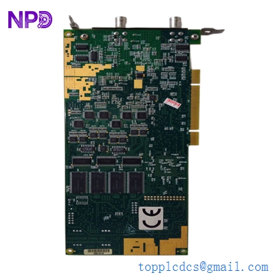
The OST-PARTS-002 is a high-precision speed sensing and regulation board assembly specifically designed for the Guardian OST-670-1 Over-Speed Trip (OST) system. This assembly acts as the core processing unit for monitoring rotational velocity, providing rapid response triggering to prevent mechanical over-speed conditions in industrial turbines and large rotating machinery.
- Compatibility: Guardian OST-670-1 Protection Systems
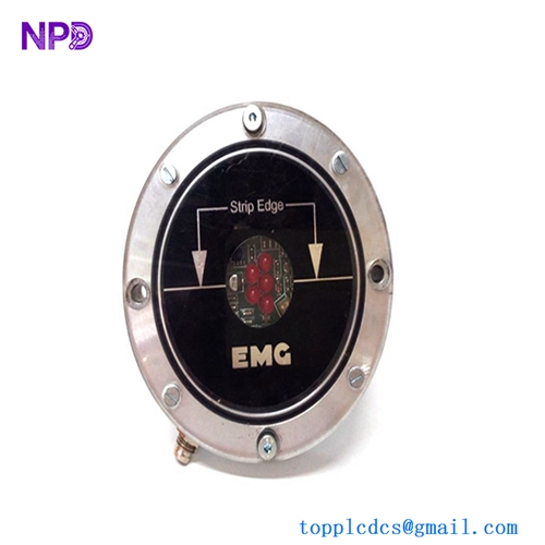
- Signal Input: Dual-channel magnetic pickup (MPU) or proximity probe inputs
- Response Time: < 20 milliseconds for trip activation
- Operating Voltage: 24V DC nominal (18-36V range)
- Threshold Settings: Multi-turn potentiometer or digital DIP switch configuration
- Output Type: High-speed relay contact and logic-level trip signals
Product Datasheet
| Feature | Specification |
|---|---|
| Model | OST-PARTS-002 |
| Associated System | Guardian OST-670-1 |
| Dimensions | 145 x 110 x 35 mm |
| Weight | 0.38 kg |
| Country of Origin | USA |
| Protection Rating | IP20 (Industrial Enclosure Required) |
| Mounting | Chassis mount via four-point standoffs |

Application Fields
This speed board assembly is a critical safety component used in:
- Power Generation: Over-speed protection for steam and gas turbines to prevent catastrophic mechanical failure.
- Oil & Gas: Monitoring of high-speed centrifugal compressors and pumps.
- Marine Propulsion: Speed regulation and safety shutdown systems for large engine sets.
- Emergency Standby Power: Ensuring diesel generators do not exceed rated RPM during sudden load shedding.
Product Instructions
- System Power Down: Ensure the Guardian OST control cabinet is fully de-energized before accessing the internal assemblies.
- ESD Safety: Handle the OST-PARTS-002 only by the edges of the PCB; use a grounded wrist strap to prevent static discharge to the logic ICs.
- Mechanical Installation: Secure the board onto the internal standoffs, ensuring all nylon or metal spacers are correctly positioned to prevent short-circuiting against the backplane.
- Wiring Integration: Reconnect the multi-pin speed sensor headers. Ensure the shielding of the MPU cables is grounded at only one end to prevent EMI interference.
- Calibration: Perform a simulated over-speed test using a frequency generator to verify that the board triggers the shutdown relay at the precise RPM setpoint defined by the plant safety protocol.
Q&A – Common Questions
Q1: Can the OST-PARTS-002 be used as a standalone tachometer? A1: While it processes speed signals, it is designed primarily as a safety trip device. For visual RPM monitoring, the board’s buffered output should be connected to an external display unit or DCS input.
Q2: What should I do if the “Status” LED on the board is flashing red? A2: A flashing red LED typically indicates a loss of signal from the speed sensor or an internal watchdog timer error. Check the continuity of the MPU cables and verify the gap between the sensor and the gear tooth.
Q3: Is this board compatible with both active and passive speed sensors? A3: The OST-PARTS-002 is standardly configured for passive magnetic pickups. If using active (Hall Effect) sensors, verify that the input jumper settings on the board are adjusted for the correct voltage threshold.
Related Product Recommendations
- Guardian OST-670-1-PS | Power Supply Module
- OST-CABLE-350 | Shielded Speed Sensor Cable Assembly
- Guardian OST-670-RLY | Mechanical Trip Relay Board
- Bently Nevada 3500/50 | Tachometer Module
- Woodward 9907-164 | MicroNet Speed Control Board