
Description
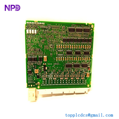
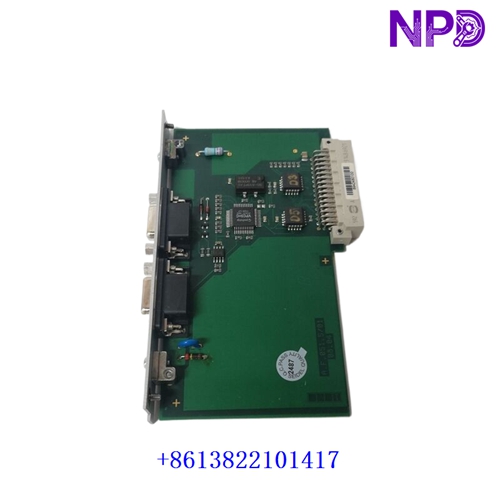
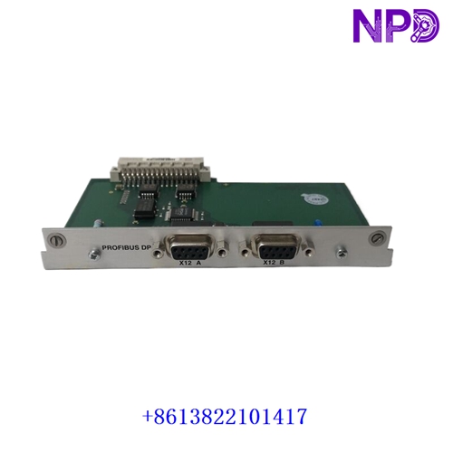
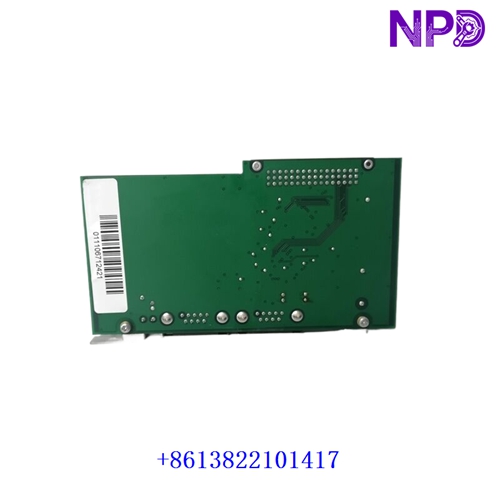
The PILZ A.F.051.501 (with revision/date code 08.04) is an internal circuit board assembly and processing module manufactured by Pilz GmbH & Co. KG for their industrial safety relay and safety controller product lines (such as the PNOZ safety relay family or PSS programmable safety controller series). Designed for safety-critical automation, it processes safety inputs (such as E-STOP buttons, safety gates, light curtains, and two-hand controls) to ensure fail-safe execution and emergency shutdown interlocks.
Key Specifications & Identification
| Attribute | Details |
| Manufacturer | Pilz GmbH & Co. KG |
| Board / Assembly Number | A.F.051.501 |
| Revision / Date Marking | 08.04 |
| Product Line | Pilz Safety Technology (PNOZ / PSS Safety Controller Series) |
| Module Category | Safety Control Logic & Signal Processing Board |
| Safety Standard Compliance | Designed to support functional safety up to SIL 3 (IEC 61508 / IEC 62061) and PL e / Cat 4 (ISO 13849-1) |
| Output Type | Dual-channel safety relay contacts or semiconductor safety outputs |
| Status Indicators | Integrated LED status indicators (Power, Channel 1, Channel 2, Fault) |
Primary System Functions
- Redundant Dual-Channel Monitoring: Evaluates incoming safety loop circuits using dual-channel cross-monitored inputs, ensuring that a single wiring fault or welded contact immediately prevents system startup.
- Fail-Safe Execution & Emergency Disconnect: Interrupts power to actuators, contactors, or drives within a deterministic response time when a safety device is actuated or a fault is detected.
- Synchronism & Cross-Circuit Detection: Performs ongoing diagnostic checks to detect shorts across channels, ground faults, or asynchronous contact closures on dual-channel safety devices.
- Feedback Loop Monitoring: Monitors external contactor auxiliary contacts (EDM / Feedback Loop) prior to resetting output channels to guarantee that external power elements have opened correctly.
Servicing & Handling Guidelines
- Strict Safety & Functional Testing: After servicing or replacing a safety module, perform a full functional proof test of all associated safety circuits (E-STOPs, safety gates, interlocks) before resuming automatic machine operation.
- Power Isolation: De-energize and lock out all 24 V DC / 230 V AC supply voltages to the safety enclosure before removing or installing module assemblies to prevent electric shock or contact arcing.
- ESD Precautions: Microprocessors, logic ICs, and optocouplers on the board are sensitive to electrostatic discharge. Always wear a grounded anti-static wrist strap during handling.
- Matching Module Variants: Verify that replacement modules strictly match the exact part number, revision level, and wiring configuration specified in the safety system’s technical documentation to maintain system safety certification.