
Description
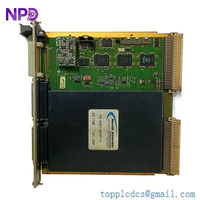
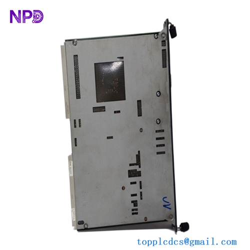
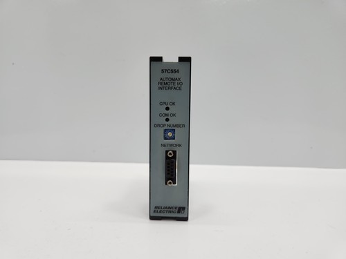
The Reliance Electric 57C554 is an essential Remote I/O Interface Module designed for the AutoMax Distributed Control System (DCS). It serves as the communications bridge between the main AutoMax processor rack and remote I/O chassis, enabling high-speed, reliable data transmission across industrial facilities. This module allows for decentralized control, reducing wiring complexity while maintaining the tight timing and synchronization required for complex motion control and automation processes.
📋 Technical Specifications
- Model Number: 57C554
- System Compatibility: Reliance Electric AutoMax
- Function: Remote I/O (RIO) Communication Interface
- Interface Type: Serial/Communication Bus
- Dimensions: Standard AutoMax rack-mount module size (approx. 11.5 x 10.5 x 1.25 inches)
- Weight: 1.8 lbs (0.82 kg)
- Country of Origin: United States
⚙️ Application Areas
- Metal Processing and Rolling Mills
- Paper and Converting Machinery
- Automated Material Handling Systems
- Distributed Industrial Control Networks
- Legacy System Modernization and Maintenance
🛠️ Operating Instructions & Guidelines
- Installation: Insert the module into the designated slot in the AutoMax I/O rack. Ensure the backplane connectors are fully seated. Tighten the top and bottom mounting screws to ensure proper grounding and mechanical stability.
- Environmental Requirements: Maintain an ambient temperature between 0°C and 60°C. Protect the module from high-humidity environments and corrosive atmospheres common in heavy industrial settings.
- Maintenance: Regularly check the physical integrity of the communication cables (typically twinax or shielded twisted pair) connected to the module. Ensure there is no evidence of fraying or oxidation at the connectors.
⚡ Power Sequence & Operation
- Power-On Sequence: 1. Ensure the remote I/O chassis is correctly addressed via the hardware dip switches. 2. Power up the remote rack’s power supply. 3. Power up the main processor rack. 4. Monitor the status LEDs on the 57C554 to confirm a “Link OK” or “Communication Active” status.
- Power-Off Sequence: 1. Stop the active control scan in the AutoMax processor. 2. Shut down the main processor power. 3. Power down the remote I/O chassis.
- Step-by-Step Operation: 1. Configure the node address on the module hardware switches. 2. Define the I/O configuration in the AutoMax programming software (AutoMax Programming Executive). 3. Perform a loop check to verify signal integrity between the local and remote I/O points. 4. Monitor the link status via the system diagnostic software.
❓ Frequently Asked Questions (Q&A)
- How do I set the remote I/O address? The address is set using the physical DIP switches located on the module board. Ensure the address matches the configuration set in the AutoMax software, or the module will not establish communication.
- What do the status LEDs signify? Typically, a steady light indicates a healthy communication link. A flashing light or a completely dark LED suggests a cable fault, address conflict, or a failure in the communication link.
- Can this module be used in any slot? No, it must be placed in the slot specifically assigned for communication or interface modules as defined by your system’s rack configuration layout.
- Is the 57C554 hot-swappable? No. Always de-energize the rack before removing or inserting the module to prevent damage to the backplane pins and the module’s circuitry.