Description
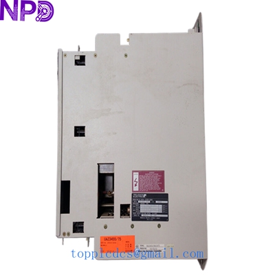
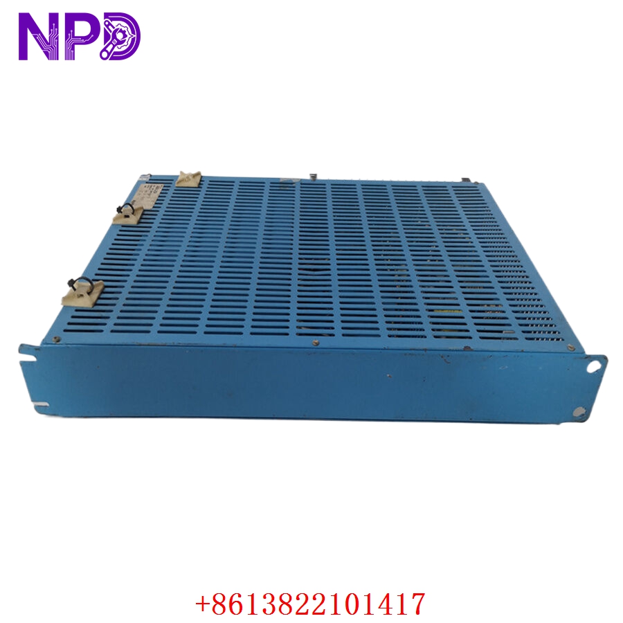
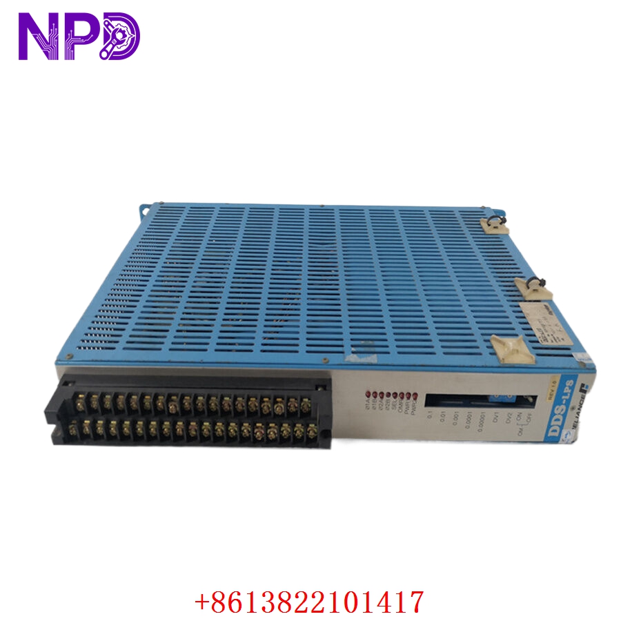
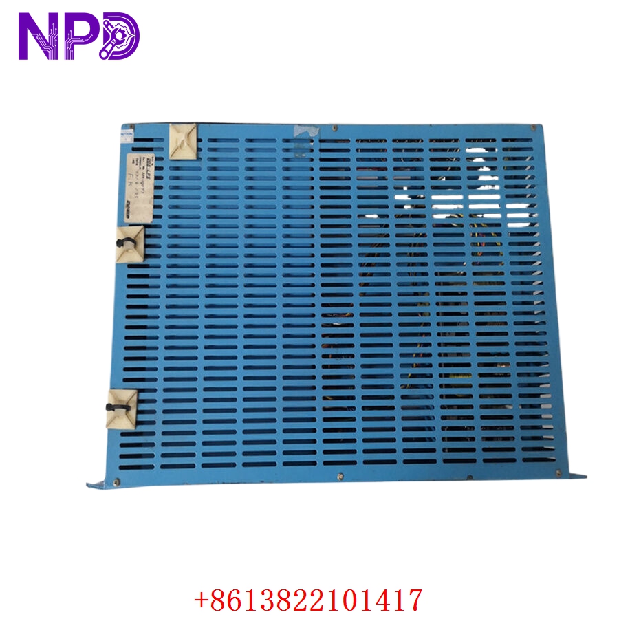
The Reliance Electric DDS-LPS is a specialized power supply module integrated into the Reliance Electric digital drive systems (such as the AutoMax or similar DCS series). It serves as the primary energy management unit for the drive cabinet, providing the regulated DC voltages required by the internal processors, logic boards, and communication interfaces to function correctly. Its robust design ensures stability for industrial motion control applications.
Technical Specifications
| Parameter | Detail |
| Model | DDS-LPS |
| Manufacturer | Reliance Electric (Rockwell Automation) |
| Device Type | Logic Power Supply Module |
| Input Power | Standard industrial AC line voltage |
| Output | Regulated DC voltage (for control logic) |
| Compatibility | Reliance Electric Digital Drive Systems |
| Mounting | Rack-mount / Drive Chassis |
| Operating Temperature | 0°C to 50°C |
Fields of Application
The DDS-LPS is widely used in heavy manufacturing environments, particularly in systems where high-precision motion and speed control are required. Common applications include:
- Web Handling Systems: Paper, film, and foil processing lines.
- Material Handling: Automated conveyor systems and cranes.
- Metal Processing: Rolling mills and strip processing lines.
- Test Stands: Dynamometer and fatigue testing machinery.
Product Introduction
The DDS-LPS acts as the foundation for the entire drive system’s “intelligence.” By converting raw AC power into clean, low-ripple DC power, it ensures that the sensitive microprocessors on the drive control boards do not experience reset loops or data corruption. It is engineered with protective circuitry to withstand the significant electrical noise generated by high-power motors and switching power stages within the drive enclosure.
Product Use Instructions
- Ensure the main input power to the drive cabinet is locked out and tagged out (LOTO).
- Inspect the module for any signs of physical damage or burnt components.
- Slide the module into the designated power supply slot in the drive rack, ensuring the rear connector is aligned correctly with the backplane.
- Secure the module using the provided mounting screws to ensure proper ground contact with the chassis.
- Once installed, verify the output voltage at the test points (if available) before connecting logic boards to the power bus.
- Power on the system and confirm the status indicators (typically a “Power Good” LED) are lit.
Product Use Precautions
Never attempt to remove or insert the DDS-LPS while the system is under load or energized, as this can cause severe damage to the backplane pins and sensitive logic circuits. Ensure that the cooling fans in the drive enclosure are fully functional, as power supplies are highly sensitive to heat buildup. Do not attempt to bypass fuses or over-voltage protection circuits, as these are critical to preventing a cascading failure of the entire drive controller.
Frequently Asked Questions (Q&A)
Q: What does it mean if the Power Good LED is not illuminated?
A: This typically indicates either a loss of input AC power, an internal fault within the power supply module, or a short circuit on the logic power bus.
Q: Can this module be repaired?
A: Due to the complexity and safety-critical nature of the power regulation circuits, component-level repair is generally not recommended. It is standard industry practice to replace the unit with a tested, refurbished, or new module.
Q: How can I prevent power supply failure?
A: The most effective preventive maintenance is keeping the cabinet filters clean to allow for proper airflow and ensuring that the electrical cabinet is free of conductive dust and moisture.
Product Operation Methods
The DDS-LPS operates autonomously once supplied with the correct input voltage. It performs an internal “power-on self-test” (POST) to ensure output voltages are within tolerance before signaling the drive system that it is ready for operation. During the drive’s runtime, it actively regulates the voltage against fluctuations in the input line and provides stable power to the control boards, allowing for consistent motor control and communication with the plant’s automation network.