Description
The Rexroth (Bosch Rexroth) VT2000-52 is a high-precision analog amplifier card designed for the control of proportional valves without electrical position feedback. It is a critical component in hydraulic motion control, translating low-level electrical command signals into controlled electrical current, which in turn drives the solenoids of proportional valves. This card ensures smooth, repeatable hydraulic movement in industrial machinery.
Technical Specifications
| Parameter | Detail |
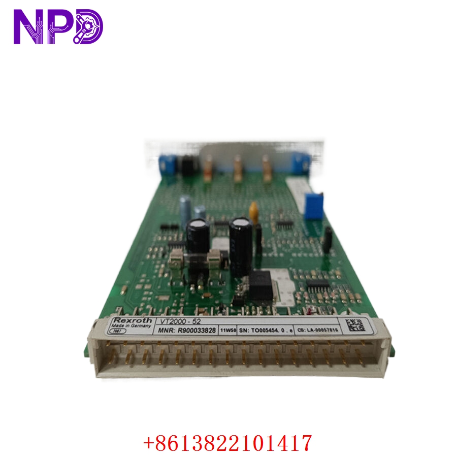
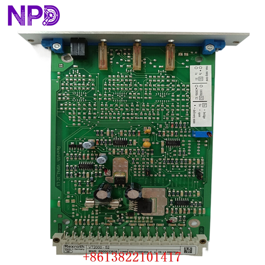
| Model | VT2000-52 |
| Manufacturer | Bosch Rexroth |
| Device Type | Proportional Valve Amplifier Card |
| Control Input | Analog (Voltage or Current) |
| Output | Pulse Width Modulated (PWM) current |
| Compatibility | Proportional valves (solenoid operated) |
| Mounting | Eurocard format (19-inch rack / card holder) |
| Operating Temperature | 0°C to 50°C |
Fields of Application
The VT2000-52 is widely used in systems where precise hydraulic force, speed, or position is required:
- Injection Molding: Precise control of injection speed and pressure.
- Presses & Forging: Maintaining exact force profiles for metal forming.
- Material Handling: Controlling smooth acceleration and deceleration of heavy hydraulic cylinders.
- General Industrial Hydraulics: Precise regulation of flow and pressure in automated test rigs.
Product Introduction
The VT2000-52 acts as the bridge between your PLC/controller and the physical hydraulic valve. It receives an analog setpoint (e.g., 0-10V or 4-20mA) and converts it into a dithered PWM signal. This “dithering” is crucial; it vibrates the valve spool slightly at a high frequency, which prevents “stiction” (static friction) and ensures the valve responds instantly and linearly to command changes.
Product Use Instructions
- Installation: Insert the card into a standard Eurocard rack. Ensure the 32-pin connector is fully seated and locked.
- Wiring: Wire your power supply (typically 24VDC), input command signal, and solenoid connections to the appropriate pins on the rear connector.
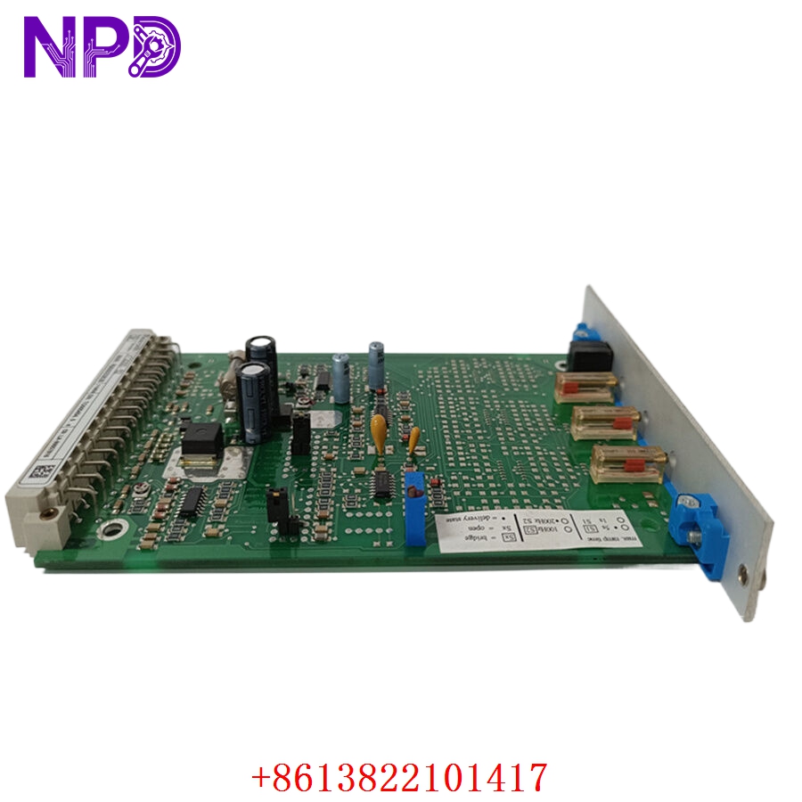
- Configuration: Use the front-panel potentiometers to adjust:
- Zero (Zero Point): Sets the threshold where the valve just begins to open.
- Gain (Sensitivity): Adjusts how much the valve reacts to changes in the input signal.
- Ramp Time (Acceleration/Deceleration): Controls how quickly the valve reaches the requested position.
- Validation: Monitor the solenoid output with a multimeter to ensure current levels stay within the valve’s specified coil rating.
Product Use Precautions
- Electrical Noise: Keep command signal wiring separate from high-current motor/solenoid wiring to prevent signal interference.
- Overheating: Ensure the card rack has adequate ventilation; analog electronics are highly sensitive to thermal drift.
- Calibration: Only adjust potentiometers using a non-conductive screwdriver to avoid short-circuiting the board components.
- Compatibility: Always match the amplifier’s output current range to the specific valve solenoid’s rated current.
Frequently Asked Questions (Q&A)
Q: My valve isn’t moving, even though the PLC is sending a signal. What should I check?
A: Check if the “Ready” or “Enable” pin on the VT2000-52 is energized. If not, the card will not output current. Also, verify the input signal at the terminal block with a multimeter to ensure it isn’t being pulled to ground.
Q: How do I know the correct ramp settings?
A: Ramp times should be set based on your application’s requirements for smooth motion. Too short, and the machine will jerk; too long, and it will feel sluggish.
Q: Is this card repairable?
A: If the board suffers a component failure (like a blown output transistor), it is generally more cost-effective to replace the card than to attempt a repair.
Product Operation Methods
During operation, the VT2000-52 receives the command, applies the programmed ramp to smooth the transition, and then drives the solenoid with a PWM signal. This ensures that the hydraulic fluid flow is controlled precisely. Periodic checks of the connections and the valve’s performance are recommended to ensure that hydraulic wear has not shifted the required calibration settings.