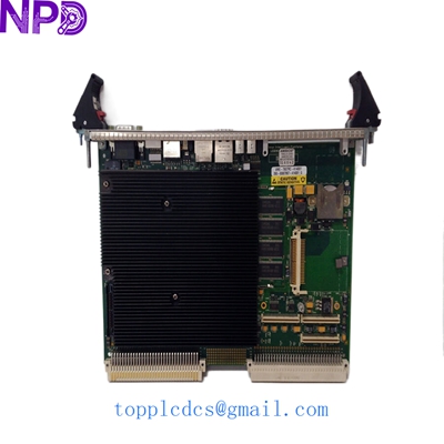
Description
- Model: SK-G9-GDB1-D292 (Part No: 347594-A01)
- Brand: Rockwell Automation / Allen-Bradley
- Series: PowerFlex 700S / PowerFlex 700 Large Horsepower Drives
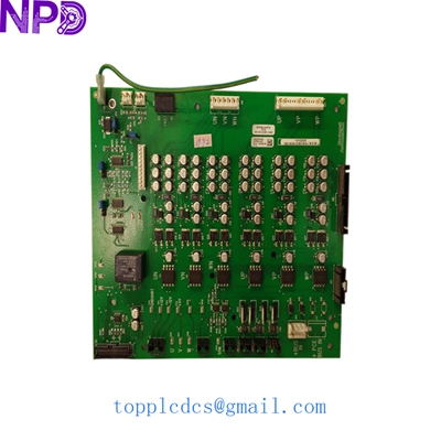
- Core Function: Gate Drive Board (GDB) responsible for firing IGBTs; New Surplus (Non-refurbished)
- Product Type: Power Electronics Drive Board
- Key Specs: Frame 9 compatible, Dual-channel gate control, High-voltage isolation
- Compatibility: PowerFlex 700S High-Performance AC Drives
- Drive Frame Size: Specifically designed for Frame 9 assemblies
- Input Control Signal: Fiber optic or high-speed ribbon interface (depending on sub-revision)
- Output Drive: High-current gate pulses for IGBT (Insulated Gate Bipolar Transistor) modules
- Isolation Voltage: Rated for 600 V class power structures
- Monitoring: Integrated desaturation detection and fault feedback
- PCB Coating: Conformal coating for industrial environment resistance
- Part Number Cross-Ref: 347594-A01 (Engineering Revision)
ROCKWELL SK-G9-GDB1-D481 347594-A05
Installation & Configuration Guide
Phase 1: Pre-Installation (Est. 20 mins)
⚠️ DANGER: LETHAL VOLTAGE
- Disconnect and lockout all incoming power to the PowerFlex drive.
- Crucial: Wait at least 15-20 minutes for the DC bus capacitors to discharge. Verify with a high-voltage meter that the bus voltage is near 0 V before touching any internal components.
- Wear a grounded ESD (Electrostatic Discharge) wrist strap. Gate drive boards are extremely sensitive to static.
Phase 2: Removal (Est. 15 mins)
- Documentation: Take high-resolution photos of all ribbon cables and fiber optic connections. Note the orientation of the gate lead wires.
- Disconnecting: Gently unplug the gate leads from the IGBT terminals. Use needle-nose pliers if necessary, but do not pull on the wires themselves.
- Unmounting: Remove the plastic standoffs or mounting screws holding the SK-G9-GDB1-D292 to the power structure.
Phase 3: Installation (Est. 20 mins)
- Verify Jumpers: Compare the jumper settings on the new 347594-A01 board with your old unit. They must match exactly for the drive to recognize the gate timing.
- Seating: Mount the board onto the standoffs. Ensure no wires are pinched underneath the PCB.
- Connections: Reattach the gate leads. Ensure they are tight; a loose gate connection can lead to immediate IGBT failure upon power-up.
Phase 4: Power-On & Testing (Est. 30 mins)
- Static Check: Before applying 480/600 V, apply only the control power (usually 24 V DC or 120 V AC) if the drive architecture allows. Check for “Gate Drive Fault” on the HIM (Human Interface Module).
- Low Voltage Test: If possible, perform a “V/Hz” test at low bus voltage to verify the switching pattern.
- Final Load Test: Apply full power and run the motor at a low RPM. Monitor the “Output Current” for balance across all three phases.
Customer Cases & Industry Applications
Case 1: Steel Mill Rolling Line Emergency Recovery A major steel producer in North America experienced a “F108 Anode/Gate Fault” on a PowerFlex 700S drive controlling a critical tension reel. The drive was a Frame 9 unit, and the factory lead time for an SK-G9-GDB1-D292 was over 20 weeks. We provided a New Surplus 347594-A01 board via Next Day Air. The mill was back in production within 36 hours. To be honest, without this “obsolete” stock, they were looking at a $200,000 upgrade to a newer drive series just to get the line moving again.
Case 2: Mining Ventilation System Maintenance An iron ore mine used PowerFlex 700S drives for their primary ventilation fans. During a scheduled maintenance window, the technician noticed heat damage on the gate drive board traces. Rather than waiting for a failure, they purchased our last SK-G9-GDB1-D292 as a preventative replacement. By swapping the board during a planned outage, they avoided an unscheduled “trip” that would have required a full mine evacuation due to air quality regulations.
Frequently Asked Questions (FAQ)
Q: Can I use a used or “pulled” board for this critical application? A: We strongly advise against it. Gate drive boards handle the high-speed switching of thousands of watts. A used board may have “weakened” capacitors or optocouplers that test fine on a bench but fail under load. Our SK-G9-GDB1-D292 is New Surplus, meaning it hasn’t endured the thermal cycling of a working drive.
Q: My board says 347594-A01, but the sticker says SK-G9-GDB1-D292. Are they the same? A: Yes. Rockwell often uses “SK-” (Service Kit) numbers for the ordering code, while the “347594” number is the actual raw PCB or assembly number. As long as these two match your existing unit, it is a direct drop-in replacement.
Q: Why did my original board fail? A: In our experience, GDB failures in Frame 9 drives are usually caused by one of three things: cooling fan failure leading to overheating, excessive vibration loosening the gate leads, or an IGBT “short” that sent high voltage back into the drive circuitry. We recommend checking your IGBTs before installing the new board to ensure they aren’t shorted.
Current Inventory Highlights
Beside the SK-G9-GDB1-D292, we have these high-value industrial modules ready for dispatch:
- Allen-Bradley www.newplcdcs.com 20-HIM-A6 (HIM Module)
- Rockwell 1756-L83E ControlLogix Processor
- Honeywell TC-PPD011 Power Supply
- ABB www.newplcdcs.com DSQC679 FlexPendant
- Bently Nevada 3500/15 Power Supply
- Siemens 6DD1607-0AA2 Application Module
- Triconex 3721 Analog Input Module
- General Electric IS200STAIH1A Terminal Board