
Description
🌐 Product Overview
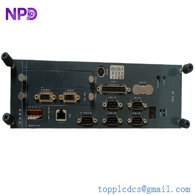
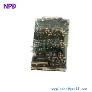
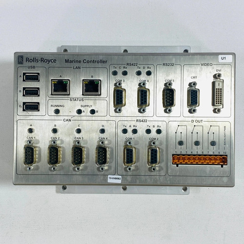
The Rolls Royce H1127.0101 is a highly specialized, marine-certified automation controller designed for integration within proprietary vessel management systems and propulsion control networks. Built to withstand the rigorous physical and environmental demands of machinery spaces, this controller processes complex algorithmic data for dynamic positioning, throttle actuation, and engine synchronization. It provides heavy-duty computing power, exceptional electromagnetic noise immunity, and deterministic response times to ensure safe navigation and steady machinery performance under volatile open-ocean conditions.
⚙️ Technical Specifications
- Series: H1127 Marine Automation Controller Component Line
- Dimensions: 240mm x 165mm x 95mm
- Weight: 2.90 kg
- Origin: United Kingdom / Norway (Depending on marine division manufacturing site)
- Processor Architecture: Dedicated industrial real-time embedded processor
- Supply Voltage: 24V DC nominal (Dual redundant inputs with a 16V to 32V DC wide operational range)
- Communication Routing: Multiple isolated CAN bus lines, RS-485 serial interfaces, and dedicated marine fieldbus channels
- Ingress Protection: IP20 (Designed for enclosed, climate-controlled console installation)
🚀 Application Fields
- Propulsion Control Systems: Regulating electronic governor systems, main engine speeds, and azimuth thruster azimuth angles.
- Vessel Management Systems (VMS): Coordinating critical auxiliary machinery, including ballast pumps, cooling water loops, and steering gear networks.
- Dynamic Positioning (DP): Serving as a localized executing node for distributed thruster commands driven by core DP computation vectors.
- Clutch and Gearbox Control: Managing automated engagement, safety interlocks, and hydraulic pressure parameters for heavy marine reduction gears.
📖 Product Instructions
- Chassis Mounting: Secure the H1127.0101 controller inside the localized equipment cabinet or main bridge console using standard DIN rails or dedicated surface-mounting brackets. Ensure the unit is grounded directly via the chassis grounding stud to the cabinet’s copper ground bus.
- I/O and Communication Hookup: Plug the pre-wired terminal blocks or round marine-grade connectors into their respective ports. Keep low-voltage data lines separated from high-voltage starter coil cables within the wiring ducts to prevent cross-talk.
- Redundancy Alignment: If deployed in a redundant configuration, connect the secondary network backbone to the auxiliary communication ports to ensure automated signal path switching in case of a main network break.
✅ Initial Startup Checklist
- Verify that both primary and secondary 24V DC power feeds supply stable, filtered voltage to the controller inputs.
- Confirm that all communication terminators (such as 120-ohm resistors for CAN bus loops) are installed correctly at the network ends.
- Turn on the cabinet breakers and confirm that the green “PWR” (Power) and “RUN” (Status) LEDs illuminate without amber or red fault flashing.
- Check that the system heartbeat indicator changes state dynamically on the main diagnostic screen, confirming data exchange with the central bridge workstation.
🛠️ Maintenance & Care
- Vibration Inspections: Check terminal block tension and mounting bracket security every six months to counteract persistent structural hull vibrations.
- Environmental Cleaning: Keep the housing free from salt-crust accumulation, oil mist, or moisture. Clean the external surfaces using a dry, anti-static microfiber cloth during scheduled vessel overhauls.
- Firmware Audits: Review internal system error codes through the service port during annual class surveys to identify transient network errors or internal memory parity warnings early.
⚠️ Safety Precautions
- Propulsion Safety Lockout: Never upload software modifications, flash firmware, or disconnect power rails while the vessel is underway or while the propulsion system is in remote control mode.
- Power Isolation: Ensure the control circuit breaker is locked and tagged out before attempting to remove or swap the controller hardware assembly.
- Static Management: Handle the unit by its external metal frame and use an ESD grounding strap when connecting data cables to protect the internal high-speed communication transceivers from static shock.
🔍 Troubleshooting & FAQ
- Q: The “COMM” LED flashes red and the remote control station reports a timeout error.
- A: This indicates a network disconnection or high error rate on the data bus. Check the serial or CAN bus wires for physical damage, verify that the cable shielding is grounded at only one end, and ensure termination resistors are intact.
- Q: The unit shuts down or reboots unexpectedly when heavy deck machinery starts up.
- A: This is typically caused by severe voltage drops or inductive spikes on the auxiliary 24V DC power grid. Install a dedicated uninterruptible power supply (UPS) or a power stabilization module to isolate the controller’s power inputs.
- Q: How can I manually force the controller into its baseline bootloader mode for firmware updates?
- A: Connect a service laptop to the designated RS-232/USB service port, hold down the recessed factory reset pin on the front panel while cycling the main power breaker, and follow the terminal emulation prompts.