
Description
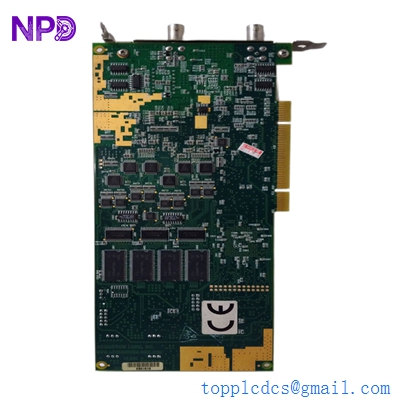
The Rosemount PWB 9240021-100G is an industrial-grade Power Supply and Communication Printed Wiring Board (PWB) assembly engineered for high-end process instrumentation, specifically optimized for advanced field transmitters or liquid analysis systems. This core circuit module performs dual-tier critical operations: converting raw auxiliary plant power into tightly regulated, low-noise DC voltage rails to feed internal processing logic, while simultaneously managing bidirectional communication data layers (such as standard HART, Foundation Fieldbus, or RS-485 Modbus protocols) to stream telemetry back to the central Distributed Control System (DCS).
⚙️ Technical Specifications
- 📐 Dimensions: 148 mm x 112 mm x 22 mm
- ⚖️ Weight: 0.34 kg
- 🌍 Country of Origin: United States
🏭 Applications
- Rosemount precision analytical and multi-variable transmitter assemblies
- Field-mounted data acquisition and process telemetry clusters
- Hazardous area hazardous field loop isolation networks
- Smart instrumentation power distribution and protocol management

🛠️ Usage Instructions
- ESD Warning: Ensure an earthed anti-static wrist strap is worn continuously while handling the board to prevent localized puncture degradation of the high-performance communication chipsets.
- Isolate all incoming power breakers before inserting or removing the terminal block interfaces to eliminate the danger of inductive voltage spikes.
- Verify that the physical hardware write-protect jumper configuration matches your plant safety protocol before attempting remote firmware or calibration adjustments.
- Avoid using standard solvent cleaners on the surface-mount logic path; clean physical debris using low-pressure dry nitrogen gas only.
🔧 Mechanical Installation Requirements
- Fixing Method: Rigidly mounts inside the instrument’s explosion-proof or weather-proof enclosure using four pre-threaded corner standoffs and specialized lock-washers to mitigate high-frequency structural vibration.
- Space Clearance: Maintain a minimum 12 mm air boundary clearance around the component face to prevent shorting against the internal metal walls of the housing shield.
- Heat Dissipation: Passive thermal design. The module relies on the casting structure of the outer instrument enclosure to act as a heatsink; keep ambient inner casing temperatures under 70°C.
🔌 Electrical Wiring Guide
- Terminal Definitions: * Terminals 1–2: Power Supply Input (Loop-powered 24V DC or external auxiliary AC/DC model dependent)
- Terminals 3–4: Redundant Data Layer Interface Contacts (HART / Modbus RS-485 lines)
- Terminals 5–6: Internal Sensor Stack Power Feed Loop
- Earth Terminal: Grounding contact tab on the outer edge plane running to the case ground
- Wire Gauge: Implement minimum 0.5 mm² up to 1.5 mm² (20 to 16 AWG) twisted, shielded, multi-strand instrumentation grade wires for external process hookups.
- Grounding Norms: Connect the field cable drain shield wire to the instrumentation grounding bus bar at the control room rack side only. Ensure the local instrument chassis ground is firmly bonded to the local structural earth grid to prevent common-mode noise corruption of the data stream.
📡 Communication Configuration
- IP Address: Not applicable on this standalone transceiver hardware level. Network configurations are mapped via software field protocols or assigned upstream through bus segment couplers.
- Station ID: Configured software-wise via standard DD/EDDL field tools, or set via hardware rotary address blocks on the card plane to assign its distinct network node profile.
- Baud Rate: Automatically adapts to match the underlying bus network architecture; supports legacy HART frequency modulation (1200 bps) up to high-speed serial bus platforms (e.g., Modbus RTU at 9600 bps or 19200 bps).
❓ Frequently Asked Questions (Q&A)
- Q: What does a flashing amber LED indicate on the 9240021-100G card face?
- A: This normally signifies active communication processing, showing that the board is cleanly transferring field telemetry packets back and forth with the master controller or handheld terminal.
- Q: Can this power supply card handle direct loop-powered 4–20 mA architectures?
- A: Yes, the 9240021-100G is flexible and engineered to support standard 2-wire loop-powered installations where power and communication are superimposed onto a single pair of wires.
- Q: Why is the master controller reporting a “HART Communication Timeout” error?
- A: Inspect the field loop for correct minimum resistance (250 ohms required for clean HART signaling), check for loose wire clamp contacts at the terminals, and verify that the cable run is not routing near high-voltage motor power leads.