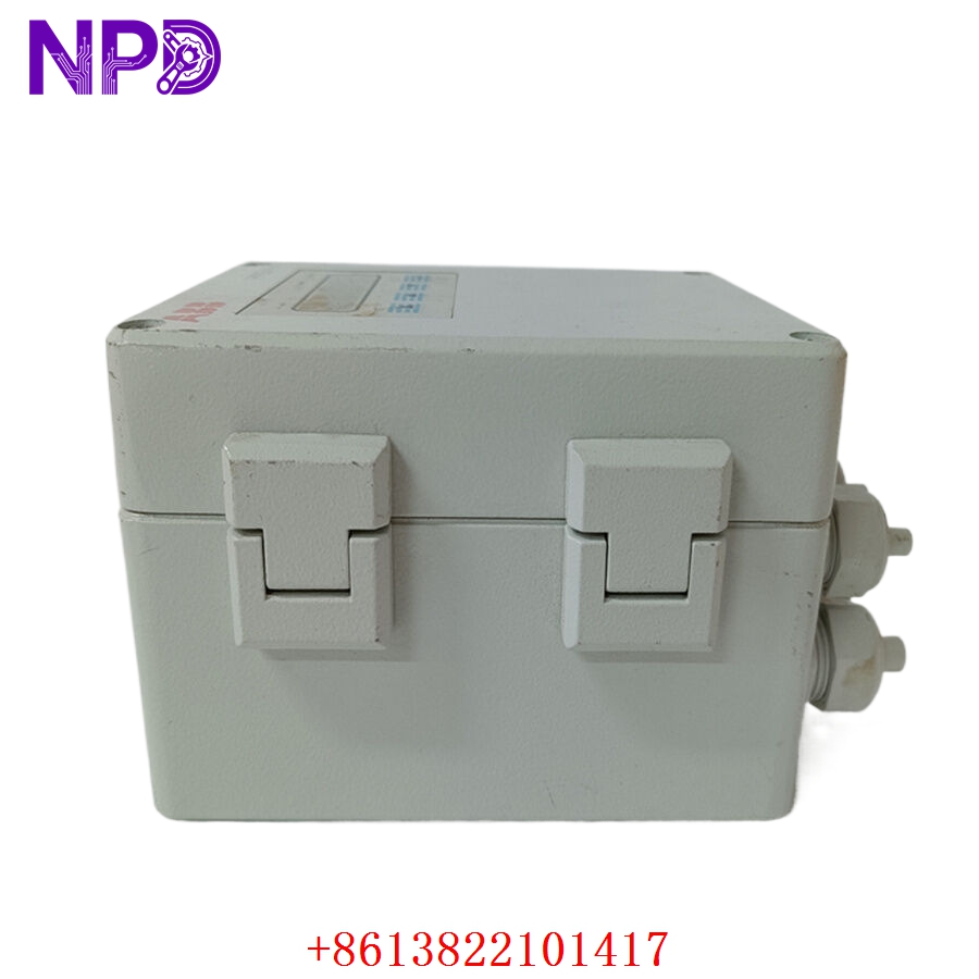

Description
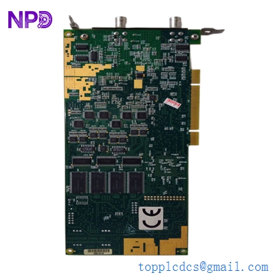
The Ross Hill Controls 0521-2500-19 is a specialized AC Control Module designed for high-power industrial applications, most notably in oil drilling rig SCR (Silicon Controlled Rectifier) drive systems. It is responsible for managing the precise triggering of power thyristors to regulate AC motor speed, torque, or power distribution. Known for its durability in the demanding environments of the energy sector, this module provides the critical synchronization required to maintain stable operations under high load.

📋 Technical Specifications
- Model Number: 0521-2500-19
- Manufacturer: Ross Hill Controls
- Function: AC Thyristor/SCR Control and Regulation
- Operating Environment: Industrial Drilling/Heavy Manufacturing
- Mounting: Standard Ross Hill control rack/cabinet
- Dimensions: 12.0 x 8.5 x 4.0 inches (Approx. module size)
- Weight: 3.1 lbs (1.4 kg)
- Country of Origin: United States
⚙️ Application Areas
- SCR Drilling Rig Power Systems
- AC Motor Variable Speed Drives (VSD)
- Industrial Power Generation Control
- Heavy-Duty Pump and Drawworks Control
- Legacy Power Conversion Retrofits
🛠️ Operating Instructions & Guidelines
- Installation: Ensure the module is installed in a climate-controlled, dust-protected SCR house or control cabinet. All high-current connections must be verified for proper torque and insulation integrity before power-up.
- Environmental Requirements: Operating temperature should be maintained within standard industrial limits (0°C to 50°C). Humidity must be kept low to prevent tracking and arcing on the sensitive PCB components.
- Maintenance: Periodic inspection of the module for signs of heat stress (discoloration on the board or connectors) is recommended. Ensure the cabinet’s cooling fans are fully functional to prevent premature component failure.
⚡ Power Sequence & Operation
- Power-On Sequence: 1. Energize the auxiliary control power (usually 24VDC or 120VAC control). 2. Verify all status LEDs are performing the expected self-test routine. 3. Apply the main power to the SCR bridge. 4. Initiate the enable signal from the operator console to begin active regulation.
- Power-Off Sequence: 1. Issue a controlled “Ramp-to-Stop” command to ensure the motor decelerates safely. 2. Remove the control enable signal. 3. Open the main power contactors to isolate the bridge from the AC supply. 4. De-energize auxiliary control circuits.
- Step-by-Step Operation: 1. Configure the pulse gate settings to match the thyristor requirements. 2. Establish a feedback loop (typically via tachometer or encoder) to the module. 3. Tune the gain and stability pots to prevent hunting or oscillation. 4. Monitor real-time output current to ensure it remains within the motor’s nameplate ratings.
❓ Frequently Asked Questions (Q&A)
- What is the significance of the “AC” designation in this module? It signifies that the module is specifically designed to manage the gating pulses for AC-side conversion, differentiating it from DC-side armature control modules.
- How do I diagnose a “Loss of Gate Pulse” error? Use an oscilloscope to monitor the gate-to-cathode waveform of the SCRs. If the signal is missing, check the ribbon cables connecting the control module to the gate driver interface for continuity.
- Can this module be used in a master-slave configuration? Yes, these modules are frequently used in coordinated drive systems; however, you must ensure that the communication/synch signals are properly terminated and shielded to avoid data jitter.
- Why does the motor chatter at low speeds? This often indicates a need for re-tuning the low-speed compensation parameters or checking for instability in the feedback signal from the motor encoder.