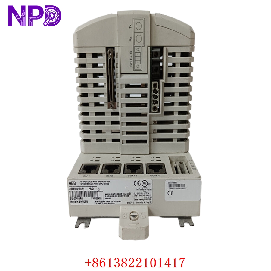

Description
The ROSS HILL CONTROLS 0521-2500-19 is a high-precision AC control module designed for SCR (Silicon Controlled Rectifier) drive systems. Primarily utilized in oil and gas drilling rig power systems, this module plays a critical role in managing AC motor speed, torque, and power distribution. It is engineered to withstand extreme industrial conditions, providing reliable phase-angle control and diagnostic monitoring for mission-critical heavy machinery.
⚙️ Technical Specifications
- Dimensions: 310 mm x 220 mm x 85 mm
- Weight: 1.2 kg
- Country of Origin: United States
- Control Input: 0-10V or 4-20mA (Configurable)
- Operating Temperature: -20°C to +70°C
- Housing: Ruggedized industrial chassis for high-vibration environments

🏗️ Application Areas
- Oil and Gas Drilling Rig AC Drive Systems
- SCR Drive Control Cabinets
- Heavy-duty Industrial Pump and Fan Control
- Synchronous and Induction Motor Management
- Power Distribution and Conversion Units
📖 Product Usage Instructions
This control module is intended for installation within a Ross Hill-compatible SCR cabinet. Ensure that the module is firmly seated into the control rack and that all ribbon cables and terminal blocks are properly secured. Due to the high-voltage nature of the equipment it controls, ensure that the cabinet is fully de-energized and verified with a voltmeter before performing any installation or maintenance tasks.
🌐 Communication Configuration Steps
- IP Address: As this is an analog-dominant control module, direct IP addressing is typically handled by an external communication gateway or a linked PLC.
- Station Number: Configure the device via the physical DIP switches located on the side of the module if being used in a multi-drive serial communication loop.
- Baud Rate: If integrated into a serial link, the baud rate must be matched to the host controller (e.g., 9600 or 19200 bps) to ensure accurate timing of firing pulses for the SCRs.
⚡ Power-Up Debugging Flow
- Confirm control power (typically 24VDC or 120VAC depending on the revision) is stable.
- Verify that the “Power” LED is illuminated solid green.
- Check the “Ready” signal; if the unit flashes red, refer to the diagnostic light pattern in the manual.
- Slowly increment the reference signal (0-10V) and monitor the “Output” LED for pulse-width modulation activity.
- Observe the firing pulse feedback at the SCR gate terminals.
✅ Initial Run Checklist
- Validate that the firing angle corresponds linearly with the input command signal.
- Inspect the feedback loop from the AC motor to ensure “Speed” and “Current” values are within nominal parameters.
- Check for any “Over-current” or “Phase Loss” alerts on the module faceplate.
- Verify that the E-Stop logic successfully interrupts the gating pulses immediately.
- Ensure heat-sink temperatures remain stable during the first 30 minutes of operation.
❓ Frequently Asked Questions (Q&A)
Q: What is the significance of the 0521-2500-19 part number? A: This specific part number defines the hardware revision and the internal logic programming tailored for Ross Hill AC drive applications. Always ensure the part number matches your existing system specs before replacement.
Q: Can I repair a faulty module at the board level? A: Because these modules rely on precision-calibrated firing circuits, board-level repair is only recommended by certified technicians. Attempting to solder components may disrupt the timing precision required for SCR switching.
Q: Why is the “Fault” LED flashing intermittently? A: Intermittent fault signals often indicate an unstable input signal or electrical noise (EMI) on the control cables. Check that your signal cables are properly shielded and grounded to the common bus.
Q: How do I ensure this module is compatible with my drive cabinet? A: Refer to your drive cabinet’s wiring schematic. Ross Hill systems have several variations; ensure that the pin-out configuration of the 0521-2500-19 matches your specific cabinet backplane.