Description
🔥 Product Overview
The SAACKE FLUS 06, part number 7-8385-527356, is a flame monitoring component used in SAACKE combustion and burner management systems. The FLUS 06 monitors the flame signal from the associated flame scanner and provides a defined flame-status output for the burner safety system.
The FLUS 06 flame detection system is designed for combustion equipment such as marine boilers, thermal oil systems, and industrial firing plants. In the SAACKE FLUS 06 UV / FLS 09 UV configuration, the FLS 09 UV scanner detects ultraviolet radiation from the burner flame while the FLUS 06 processes the scanner signal and provides the flame status to the control system.
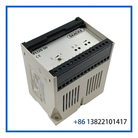
⚙️ Key Features
- SAACKE FLUS 06 flame monitoring unit
- Part number 7-8385-527356
- Designed for burner flame supervision
- Compatible with the SAACKE flame detection system architecture
- Supports flame-present / flame-off status indication
- Self-monitoring design with redundant signal processing
- Front-panel LED indication for flame status and signal intensity
- Potential-free safety output contact
- Suitable for marine and industrial combustion applications
- DIN-rail or control-panel installation
📋 Product Datasheet
| Parameter | Specification |
|---|---|
| Brand | SAACKE |
| Model | FLUS 06 |
| Series | FLUS 06 Flame Detection System |
| Product Name | Flame Monitor |
| Part Number | 7-8385-527356 |
| Detection System | UV Flame Detection / Flame Monitoring |
| Operating Voltage | 230 VAC (-15% / +10%) |
| Power Consumption | Approx. 5 VA |
| Operating Temperature | -10°C to +60°C |
| Weight | Approx. 500 g |
🛠️ Application & System Integration
The FLUS 06 is installed as part of the flame detection chain between the burner flame sensor and the combustion safety/control system. In the UV configuration, the associated FLS 09 UV flame scanner observes the burner flame and converts the detected UV radiation into an electrical signal. The FLUS 06 evaluates this signal and provides the corresponding flame status.
The monitor uses self-monitoring signal processing to improve the reliability of flame supervision. Flame status is indicated by front-panel LEDs, while the safety-related output contact can be integrated into the burner control circuit.
For marine boiler applications, the FLUS 06 can form part of a SAACKE burner management arrangement where reliable flame detection is required before continued fuel supply is permitted.
🔧 Installation & Maintenance
The flame monitor is normally installed inside a control cabinet, control panel, or suitable control box. It can be mounted on a top-hat rail or through mounting holes depending on the installation version.
The FLUS 06 itself is designed to be maintenance-free. The front panel can be cleaned with an appropriate soft cloth and approved cleaning agents.
The associated flame scanner requires more attention because contamination of its optical lens can reduce the flame signal. During maintenance, the flame monitoring safety function must be handled carefully because removing the scanner can temporarily disable flame supervision.
⚠️ Safety Notes
The FLUS 06 is a safety-related combustion monitoring component. Replacement should be performed by qualified personnel familiar with the burner and combustion safety system.
After replacing a flame scanner or flame monitor, the flame-failure safety function should be checked according to the applicable SAACKE commissioning or service procedure. Do not open or attempt to repair a defective safety-related flame monitor; replacement with a suitable original or approved spare part is recommended.
❓ Frequently Asked Questions
Q1: What is the function of the SAACKE FLUS 06?
A1: It evaluates the flame signal from the associated flame scanner and provides flame-present or flame-off status to the burner safety/control system.
Q2: Is FLUS 06 a flame scanner?
A2: The FLUS 06 is the flame monitor. In the UV flame detection arrangement, the FLS 09 UV performs the optical flame-scanning function and the FLUS 06 processes its signal.
Q3: What power supply does the FLUS 06 use?
A3: The documented FLUS 06 UV version operates from approximately 230 VAC, with a specified operating tolerance of -15% / +10% and approximately 5 VA power consumption.
Q4: Where is the FLUS 06 installed?
A4: It is normally installed in the burner control cabinet, control panel, or control box rather than directly at the burner flame sighting position.
Q5: Can a defective FLUS 06 be repaired?
A5: SAACKE documentation treats the flame monitor as a safety-related component. A defective unit should be replaced rather than opened or repaired in the field.
Q6: What should be checked before replacing this module?
A6: Verify the exact part number, flame detection configuration, revision, burner control architecture, wiring, and associated flame scanner before installation.
⭐ Related SAACKE Models & Components
- SAACKE FLS 09 UV Flame Scanner
- SAACKE FLS 09 UV-5 Flame Scanner
- SAACKE FLS 09 UV-5L Flame Scanner
- SAACKE FLUS 06 UV Flame Monitor
- SAACKE FLUS 06 Infrared Flame Monitor
- SAACKE FLS 07 Flame Scanner
- SAACKE RSE-P Burner Controller
- SAACKE RSE-P II Compact Controller
- SAACKE ZLE 52c Oil Igniter
- SAACKE DSB 158 Pressure Switch
📦 Replacement Recommendation
When purchasing a replacement for an existing FLUS 06 installation, the complete part number 7-8385-527356 should be matched against the existing unit. Also verify the flame scanner type, system revision, electrical connections, and burner application before commissioning.