
Description
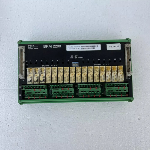
The SAM Electronics BRM 2200 is a marine-grade communication and receiver interface module engineered for integrated bridge systems (IBS) and vessel automation architectures. This specialized hardware card manages high-speed serial data distribution, telemetry bus concentration, and signal conditioning between navigational computers, voyage data recorders (VDR), and remote engine room automation subsystems. Built to naval specifications, it ensures deterministic communication frames and continuous data logging capabilities during demanding sea voyages.
Technical Specifications
- Model ID: BRM 2200
- Device Type: Bridge Data Receiver / Bus Communication Card
- Dimensions: 175 mm x 120 mm x 24 mm
- Weight: 0.35 kg
- Country of Origin: Germany
- Power Demand: 24 VDC (internal rack-bus powered)
- Interface Arrays: Redundant serial data channels, proprietary fieldbus networks, and isolated optocoupler circuits
Application Areas
📡 Integrated Bridge Navigation and Radar Consoles
🚢 Voyage Data Recorder (VDR) Telemetry Bridges
🌊 Marine Automation Central Control Racks
🏗️ Shipboard Alarm, Monitoring, and Control Systems (AMCS)
⚓ Transceiver Data Signal Concentration Units
Operational Guidelines
Power-Up / Power-Down Sequence
- Startup: Isolate the main electronics rack or console housing from active electrical mains. Align the BRM 2200 circuit card with the backplane guide rails, slide it into position until the multi-pin connector locks into place, and secure the front faceplate screws. Apply rack logic power. Monitor the startup sequence; the green status LED will pulse rapidly during system memory checks and settle into a rhythmic blinking pattern once it secures a communication sync with the master processor.
- Shutdown: Deregister the specific communication node or slot interface from the active marine station software to prevent unexpected bus timeout alarms. Turn off the primary power breaker feeding the interface sub-rack. Allow all residual electrical potential to discharge completely, and utilize specialized card pullers and an anti-static bag to extract the module.
Step-by-Step Standard Operation
- Address Assignment: Check and configure the onboard hardware dip-switches or jumpers to establish the correct node address identification before slotting the unit into the rack.
- Backplane Integration: Insert the module into the designated slot of the marine automation cabinet while wearing a properly grounded ESD wrist strap.
- Data Bus Landing: Ensure external data feeds from navigation instruments are safely landed onto the corresponding terminal blocks linked to this card slot.
- Signal Mapping: Power on the node and use the system engineering terminal to check that incoming data packets match the configured bit rate and parity rules.
- Channel Activation: Put the communication loop live to start continuous telemetry forwarding to the bridge visualization monitors and backup logs.
Frequently Asked Questions
Q: What is indicated by a flashing amber or red “TX/RX” LED on the module faceplate? A: A flashing amber light usually denotes a data framing error or transmission collision on the bus, whereas a solid red LED points to a complete transceiver hardware failure or an address conflict. Check terminal settings and software configurations.
Q: Can this card be pulled out or hot-swapped while the navigation bridge console is live? A: No. Hot-swapping the BRM 2200 can introduce voltage transients that risk corrupting shared communication lines or freezing the central processing bus. Always power down the specific card cage first.
Q: Does the BRM 2200 require external software calibration? A: The board functions as a hardware-level data link and transceiver interface, meaning it does not store local sensor calibration tables. All scaling and interpretation parameters are configured directly within the vessel’s master automation software.