
Description
📝 Product Overview
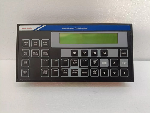
The Sam Electronics LOP 2200 is a rugged, marine-grade Local Operator Panel specifically engineered for decentralized monitoring and control within comprehensive shipboard automation systems. Functioning as a high-performance terminal for vital machinery and propulsion auxiliary components, this unit bridges the gap between field sensors and the central automation network. It delivers real-time data processing, precise parameter visualization, and quick local command override capabilities directly at the machinery site.
⚙️ Technical Specifications
- 📐 Dimensions: 280 mm x 210 mm x 85 mm
- ⚖️ Weight: 3.4 kg
- 🌍 Country of Origin: Germany
🚢 Applications
- Marine diesel engine and auxiliary machinery tracking
- Ballast water and fuel oil transfer control stations
- Power management system (PMS) localized monitoring
- Shipboard pump and compressor safety interlocking loops
🛠️ Usage Instructions
- Verify that the local operating mode switch is locked in “Remote” during normal automated sailing, and switch to “Local” only for authorized maintenance overrides.
- Use the integrated keypad and function keys to cycle through diagnostic pages and review real-time sensor parameters.
- Wipe the protective display overlay only with a soft, damp cloth; avoid abrasive solvents that may degrade anti-glare coatings.
- Check the built-in system health LED indicators periodically to confirm error-free subsystem synchronization.
🔧 Mechanical Installation Requirements
- Fixing Method: Front panel flush mounting into control desk consoles or engine room cabinet doors using integrated retaining clamps.
- Space Clearance: Maintain a clear rear zone of at least 70 mm to allow safe routing for heavy-duty industrial wiring harnesses and communications drop cables.
- Heat Dissipation: Ensure the direct environment utilizes natural or forced air convection, preventing internal enclosure air temperatures from climbing past 55°C.
🔌 Electrical Wiring Guide
- Terminal Definitions:
- Terminals 1-2: Redundant 24V DC Main & Backup Power Input (+/-)
- Terminals 3-6: Isolated CAN-Bus / Serial fieldbus interface lines
- Terminals 7-12: Configurable Digital / Analog channel terminations
- Protective Earth (PE): Heavy-duty copper stud weld on the rear chassis
- Wire Gauge: Employ 0.75 mm² to 1.5 mm² (18-16 AWG) shielded twisted-pair cables for signal paths and 2.5 mm² (14 AWG) for power supply connections.
- Grounding Norms: Connect the rear chassis grounding stud directly to the ship hull or local console copper ground plate using a thick, flat braided strap to minimize high-frequency electromagnetic noise.
📡 Communication Configuration
- IP Address: Default setup via secondary Ethernet board is 192.168.2.200 (subnet 255.255.255.0) for interfacing with upstream ship workstation infrastructure.
- Station ID: Defined dynamically via software setup menus or via binary physical switch blocks on the internal card to prevent node address collisions.
- Baud Rate: Auto-detecting configuration profiles for CAN/fieldbus communication operating at standard 250 kbps or 500 kbps modes.
❓ Frequently Asked Questions (Q&A)
- Q: What should I check if the LOP 2200 loses communication with the bridge system?
- A: Inspect the network status LEDs on the rear connection board, check the condition of the bus termination resistors, and verify that the station ID has not been accidentally altered.
- Q: Can this panel be installed on open, weather-exposed decks?
- A: No, the front panel carries a high IP rating suitable for damp engine rooms and bridge environments, but it requires an external weatherproof enclosure if exposed directly to sea spray and rain.
- Q: How do I handle a “Sensor Loop Fault” notification on the local display?
- A: This indicates a broken wire or short-circuit condition on one of the connected 4-20mA or digital field inputs. Isolate the corresponding channel terminals and check field instrument power loops.