
Description
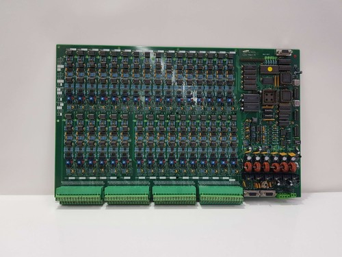
The Samsung LCU-REV 1.5 (PCB B40-2317) is an industrial controller board designed for system management and signal routing within Samsung-manufactured electronic or automation equipment. It serves as a vital logic interface, processing input data from sensors and executing output commands to peripheral components. This board is engineered for stability in specialized machinery and provides high-density signal integration to maintain operational efficiency.
📋 Technical Specifications
- Model Number: B40-2317
- Board Revision: LCU-REV 1.5
- Manufacturer: Samsung
- Function: Logic Control and Signal Integration
- Mounting Type: Enclosure/Rack Integration
- Dimensions: 7.5 x 5.0 x 1.0 inches (Approx.)
- Weight: 0.6 lbs (0.27 kg)
- Country of Origin: South Korea
⚙️ Application Areas
- Industrial Automation and Control Systems
- Specialized Electronic Equipment Drives
- Sensor Data Acquisition Modules
- Logic Processing for Manufacturing Machinery
- Legacy System Component Replacement
🛠️ Operating Instructions & Guidelines
- Installation: Always handle the PCB by its edges. Ensure the card is inserted into the designated chassis slot with firm, even pressure. Verify that the alignment tabs are locked before applying power to prevent backplane contact damage.
- Environmental Requirements: Keep the operating environment between 5°C and 45°C. Avoid high-humidity areas, as moisture can lead to short circuits across the fine traces of the LCU-REV 1.5 board.
- Maintenance: Ensure the cooling system of the main equipment cabinet is clean. Dust accumulation on the PCB can act as an insulator, leading to localized overheating. Use an ESD-safe brush to remove dust during annual inspections.
⚡ Power Sequence & Operation
- Power-On Sequence: 1. Verify that all external harness connectors are properly seated on the PCB pins. 2. Apply the system-level control voltage (typically 5V or 24V depending on the host device). 3. Wait for the host system to initialize; check the status LEDs on the board for a “Ready” heartbeat.
- Power-Off Sequence: 1. Perform a software shutdown via the host controller interface. 2. Remove the main power source from the machine. 3. Wait for internal capacitors to bleed off (approx. 30 seconds) before removing the board.
- Step-by-Step Operation: 1. Link the board to the main system bus. 2. Verify signal integrity using the system diagnostic software to ensure all I/O channels are communicating. 3. Monitor the board temperature during the first hour of operation under load to confirm normal thermal behavior.
❓ Frequently Asked Questions (Q&A)
- How do I identify if the board has failed? Common failure signs include “No Communication” errors on the main system HMI, or the PCB status LED blinking an irregular error pattern.
- Is the REV 1.5 interchangeable with other revisions? Generally, no. PCB revisions often contain changes to component placement, circuitry, or firmware compatibility. Always match the “LCU-REV 1.5” and “B40-2317” markings exactly to ensure compatibility.
- Can I solder components onto this board? It is not recommended. These boards use multi-layer PCB technology, and improper soldering can create hidden shorts or intermittent connections that are extremely difficult to diagnose.
- What is the most common cause of damage to this board? Static discharge (ESD) during handling and power spikes from the main power supply are the two most common causes of board failure. Always use a ground strap when servicing.