Description
📋 Product Overview
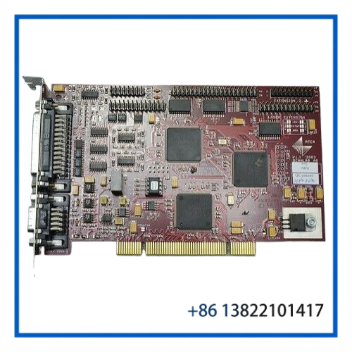
The SCANLAB RTC4 V1.1, identified as RTC 15878, is a dedicated PC interface and real-time control board for industrial laser processing systems. It is designed to coordinate scan heads, laser sources, and external machine components with precisely timed control signals.
Unlike a conventional PLC or general-purpose motion card, the RTC4 is specifically built around laser processing requirements. SCANLAB describes the RTC4 family as providing synchronized control of scan systems and lasers, including vector and bitmap processing, image-field correction, and processing-on-the-fly applications.
⚙️ Key Features
- SCANLAB RTC4 real-time laser control platform
- Version 1.1
- Identification: RTC 15878
- PC interface board for scan heads and laser systems
- Real-time synchronization of scan system and laser
- 16 digital inputs
- 16 digital outputs
- Programmable laser control signals
- Supports vector and bitmap processing
- Real-time control of external components
- Automatic image-field correction
- Support for processing-on-the-fly applications
- Windows DLL-based software interface
- Designed for integration into industrial laser processing equipment
SCANLAB’s original RTC4 documentation identifies the board as a PC interface board for real-time control of scan heads and lasers.
📊 Product Datasheet
| Parameter | Specification |
|---|---|
| Brand | SCANLAB |
| Product Family | RTC4 |
| Model | RTC4 V1.1 |
| Identification | RTC 15878 |
| Product Type | PC Interface / Laser Control Board |
| Main Function | Real-time control of scan heads and lasers |
| Digital Inputs | 16 |
| Digital Outputs | 16 |
| Laser Control | Programmable laser signals |
| Processing | Vector and bitmap processing |
| Scan System Control | Supported |
| Image Field Correction | Supported |
| Processing on the Fly | Supported |
| Software Interface | Windows DLL |
| Country of Origin | Germany |
| Condition of Listed Unit | Used |
The RTC4 platform also supports optional expansion functions and interfaces depending on the installed configuration. Exact board options should be checked against the physical board and available accessories.
🔌 Operating Function
The RTC4 sits between the host computer and the laser-processing hardware.
A typical system can be represented as:
Industrial PC → SCANLAB RTC4 → Scan Head / Laser → Processing System
The board receives processing instructions from application software and generates the timing-sensitive commands required by the scan system and laser.
One important function is synchronization. The RTC4 is designed to coordinate scanner movement and laser activation so that the laser output corresponds to the programmed processing path. This is particularly important for marking, engraving, welding, cutting, and other applications where the laser must be switched at precise points during scanner movement.
SCANLAB also documents communication with digital scan heads, including access to information such as scan-axis position, speed, amplifier current, motor temperature, operating hours, serial number, and scan-head identification when supported by the connected hardware.
🧠 Laser Control Functions
The RTC4 provides several laser-related control signals. The original documentation identifies signals including:
- LASERON
- LASER1 / Q-Switch
- LASER2 / First Pulse Killer
- Stand-By1
- Stand-By2
The laser signal logic can be configured through the board’s jumper settings, with active-low or active-high TTL logic available for the applicable signals.
This makes the board suitable for integration with different laser control architectures, but the signal level and wiring should always be matched to the particular laser source before commissioning.
🔧 Installation & Configuration
The RTC4 is normally installed as part of a computer-controlled laser-processing system.
1. Hardware Inspection
Before installation, inspect:
- PCB surface
- Edge connector
- Laser interface connectors
- Scan-head interface
- Digital I/O connections
- Jumper configuration
- Mounting hardware
- Signs of oxidation or physical damage
Because the supplied unit is used, checking the board before installation is recommended.
2. Software Installation
The RTC4 requires the appropriate SCANLAB RTC software and driver environment. SCANLAB continues to provide RTC4 software packages and drivers for RTC4 control boards.
The original RTC4 manual references the RTC4 DLL and associated firmware/DSP components, so software, DLL, DSP, and firmware versions should be considered together when commissioning an older board.
3. Scan Head Configuration
Connect the appropriate SCANLAB scan head and verify communication before enabling laser output.
Confirm:
- Scan-head type
- Digital interface
- Axis configuration
- Feedback/status communication
- Required scan-head parameters
4. Laser Configuration
Before enabling the laser, verify the laser control interface and signal polarity.
Do not assume that another RTC4 board has identical jumper settings. The laser signal logic is configurable, and incorrect signal polarity can cause unexpected laser behavior.
5. Functional Test
A sensible commissioning sequence is:
- Install the board with system power removed.
- Install the correct RTC4 driver/software.
- Confirm the board is recognized by the host computer.
- Establish communication with the scan head.
- Test scanner movement without laser emission.
- Verify digital I/O.
- Verify laser-control signals.
- Perform a low-power test.
- Run a simple marking/vector test.
- Confirm synchronization between scanner movement and laser output.
Laser safety procedures must be followed throughout the test process.
🧰 Maintenance Recommendations
The RTC4 is an electronic control board, so maintenance is mainly preventive rather than mechanical.
PCB inspection
- Keep the board clean and dry.
- Check for dust accumulation around connectors.
- Inspect the edge connector for oxidation.
- Look for damaged components or solder joints.
- Check for signs of overheating.
System inspection
- Verify the PC interface remains stable.
- Check scanner communication.
- Monitor unexpected digital I/O behavior.
- Confirm laser-control timing.
- Record software and firmware versions after a successful installation.
Storage
If the board is kept as a spare, use an ESD-safe package and a dry storage environment. Avoid repeatedly installing and removing the board without proper ESD protection.
❓ FAQ
What is the SCANLAB RTC4?
It is a PC interface board designed for real-time control of laser scan heads and laser sources.
What does RTC 15878 identify?
RTC 15878 is the identification associated with the listed RTC4 V1.1 board. The supplied eBay listing specifies the model as “RTC4 V1.1 RTC 15878.”
How many digital I/O points does the RTC4 provide?
The RTC4 provides 16 digital inputs and 16 digital outputs for real-time control of external components.
Can it control a laser directly?
The RTC4 provides dedicated laser-control signals and interfaces with laser systems, but the actual laser source must be electrically compatible with the RTC4 interface and configured correctly. It should not be treated as a standalone laser power supply.
Can it control a SCANLAB scan head?
Yes. The RTC4 is specifically designed for real-time control of scan heads, and SCANLAB documents communication with digital scan heads and their status information.
Is RTC4 V1.1 compatible with current SCANLAB systems?
Compatibility depends on the scanner, laser, software, PC operating system, and interface configuration. RTC4 is an older generation compared with RTC5 and RTC6. SCANLAB still provides RTC4 software, but system-level compatibility should be checked before purchasing for a new machine.
Is the listed board new?
No. The supplied eBay listing identifies the unit as Used.
🔄 Related SCANLAB Models
- SCANLAB RTC3
- SCANLAB RTC4
- SCANLAB RTC4 PCIe
- SCANLAB RTC4 Ethernet
- SCANLAB RTC5
- SCANLAB RTC5 PCI
- SCANLAB RTC5 PCIe
- SCANLAB RTC6 PCIe
- SCANLAB RTC6 Ethernet
- SCANLAB RTC6 EtherBox
These products belong to the SCANLAB RTC control-board family, but interface technology, software compatibility, and system architecture differ between generations. They should not be treated as direct drop-in replacements without checking the complete laser-processing system.
🏭 Typical Applications
The RTC4 can be found in computer-controlled laser processing systems such as:
- Laser marking
- Laser engraving
- Laser cutting
- Laser welding
- Semiconductor manufacturing
- Precision micromachining
- Industrial laser processing
- Medical-device laser processing
- PCB and electronics processing
- High-speed galvo scanning systems
Its main advantage in these applications is the ability to synchronize scanner movement, laser output, and external machine signals in real time.
Application Summary
The SCANLAB RTC4 V1.1 RTC 15878 is a specialized laser-processing control board rather than a general-purpose industrial I/O card. It provides the real-time interface between a host computer, scan head, laser source, and external equipment.
For legacy laser systems, the RTC4 can be especially useful when maintaining an existing machine where the original control architecture depends on the RTC4 software and interface. When replacing a board, the most important checks are the exact RTC4 revision, interface type, software/driver version, scan-head model, laser interface, and installed options.