Description
🔹 Product Overview
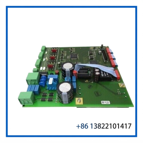
The SICK 2017506 is a SICK circuit board identified by part number 2017506. Available references associate this part number with SICK / SICK OPTIC ELECTRONIC equipment, and it is also listed in industrial repair and spare-parts catalogs as a SICK component.
Because the available identification does not provide enough information to reliably assign a specific sensor, controller, or machine family, the board should be matched using the complete part number, PCB markings, connector arrangement, and the host SICK device before replacement.
This makes the 2017506 particularly suitable for maintenance inventory and repair of existing SICK equipment where the original circuit board needs to be replaced.
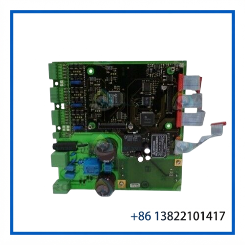
⚙️ Key Features
- Original SICK industrial circuit board
- Part number: 2017506
- SICK / SICK OPTIC ELECTRONIC identification
- PCB assembly for compatible SICK equipment
- Intended for equipment repair and replacement
- Suitable for maintaining legacy SICK systems
- Compact electronic-board construction
- Connector and circuit layout should be matched before installation
- Useful as a maintenance spare for reducing equipment downtime
📋 Product Datasheet
| Parameter | Specification |
|---|---|
| Brand | SICK |
| Model / Part Number | 2017506 |
| Product Type | Circuit Board |
| Product Name | Industrial Electronic Circuit Board |
| Associated Manufacturer | SICK / SICK OPTIC ELECTRONIC |
| Application | SICK industrial equipment |
| Installation | Internal equipment PCB assembly |
| Dimensions | Verify from actual board |
| Weight | Verify from actual board |
| Power Supply | Host-equipment dependent |
| Condition | Verify actual listing condition |
🔧 Control & Equipment Integration
The 2017506 should be considered a replacement circuit board, rather than a universal PLC module. Its electrical function is determined by the SICK equipment in which it is installed.
When integrating a replacement board, the following should be checked:
- Host equipment model
- PCB part number
- PCB revision
- Connector locations
- Cable and harness configuration
- Sensor or actuator connections
- Supply voltage supplied by the host unit
- Existing parameter or calibration data
- Firmware or device configuration where applicable
For older SICK systems, maintaining the exact board version can be important because visually similar circuit boards may use different component configurations or connector assignments.
🔌 Electrical & Interface Considerations
Before applying power to a replacement 2017506 board, verify the electrical configuration of the complete assembly.
Recommended checks include:
- Confirm the board part number.
- Compare PCB markings with the removed board.
- Check all connectors for matching positions.
- Inspect cables for damaged pins or insulation.
- Verify the host equipment supply voltage.
- Check for contamination, corrosion, or bent contacts.
- Confirm that no configuration jumpers or switches have been changed.
- Install the board only in its specified equipment position.
Do not apply an external power supply directly to the board unless the applicable SICK equipment documentation specifically permits it.
🏭 Typical Maintenance Applications
The SICK 2017506 can be useful in maintenance environments involving SICK industrial sensing and automation equipment, including:
- Factory automation
- Machine monitoring
- Industrial sensor systems
- Material handling equipment
- Production machinery
- Optical inspection systems
- Packaging machinery
- Conveyor automation
- Legacy SICK control equipment
The exact application should be confirmed from the original equipment and PCB markings rather than inferred from the part number alone.
🔄 Replacement Compatibility
For a reliable replacement, compare the following information between the installed board and the spare:
Required identification
- SICK part number: 2017506
- PCB revision
- Manufacturer markings
- Connector layout
- Component layout
- Host-device model
- Existing cable harness
- Original equipment configuration
A board with a similar appearance should not automatically be considered interchangeable. Even minor PCB revisions can change connector assignments, electrical characteristics, or equipment compatibility.
🛠️ Installation & Maintenance
Before Installation
- Disconnect the host equipment from its power source.
- Follow the machine’s lockout/tagout procedure.
- Allow stored electrical energy to discharge.
- Record all connector positions.
- Photograph or document the original installation if necessary.
- Compare the replacement PCB with the removed board.
Installation
- Remove the original board according to the host equipment service procedure.
- Inspect the mounting points and connectors.
- Confirm the replacement part number 2017506.
- Install the PCB without forcing connectors or mounting hardware.
- Reconnect each cable to its original position.
- Inspect the completed installation before energizing the system.
- Power the equipment and check for diagnostic or status indications.
- Verify normal sensor/equipment operation.
Maintenance
Store spare circuit boards in antistatic packaging and keep them away from moisture, dust, conductive contaminants, and excessive temperature. Avoid touching PCB contacts and exposed components unnecessarily.
🔍 Troubleshooting Guide
Equipment does not start after board replacement
- Verify the board is correctly seated.
- Check all connectors.
- Confirm the host-equipment supply voltage.
- Inspect for damaged pins or cables.
- Confirm that the replacement board matches the original part number.
SICK equipment reports a hardware fault
- Check PCB revision and configuration.
- Inspect connectors and harnesses.
- Compare the replacement board with the original board.
- Check the host equipment’s diagnostic information.
Sensor or machine functions are incorrect
- Verify signal wiring.
- Check connector positions.
- Confirm that the replacement board is intended for the exact host equipment.
- Check machine parameters or calibration data where applicable.
Intermittent operation occurs
- Inspect connectors for oxidation or loose contacts.
- Check cable strain and mechanical vibration.
- Look for contamination or physical damage on the PCB.
- Verify the host equipment power supply.
❓ FAQ
Q: What is SICK 2017506?
A: It is a SICK circuit board identified by part number 2017506 and used as a replacement electronic assembly for compatible SICK equipment.
Q: Is 2017506 a PLC I/O module?
A: No. It is identified as a circuit board rather than a standard PLC CPU or I/O module.
Q: What equipment does 2017506 fit?
A: The exact host equipment should be confirmed from the original PCB, equipment model, connectors, and revision. The part number alone is not sufficient to guarantee compatibility.
Q: Is SICK 2017506 still used in industrial equipment?
A: It can be relevant to legacy SICK equipment and maintenance applications where the original electronic board needs replacement.
Q: Can another SICK circuit board replace 2017506?
A: Not without compatibility verification. Matching the complete part number and board revision is recommended.
Q: What should I provide when requesting a replacement?
A: The complete 2017506 part number, a clear photo of the PCB label, connector side, and the SICK host-device nameplate are useful for confirming the correct replacement.
📦 Recommended Related SICK Models & Components
- SICK 2015801 — Circuit Board
- SICK 2015802 — Circuit Board
- SICK 2016708 — Electronic Component
- SICK 4028376 — Circuit Board
- SICK 4029030 — Electronic Board
- SICK 4033027AEO — Circuit Board
- SICK 4039385 — Circuit Board
- SICK LPX11 2029246 — Circuit Board
- SICK 1016472 — Terminal Control Unit
- SICK 1026220 — Power Supply Module
💡 Spare-Part Recommendation
For plants operating older SICK automation and sensing equipment, keeping a correctly identified 2017506 spare can shorten repair time when an electronic board failure occurs.
For inventory control, record the complete part number, PCB revision, host SICK equipment model, connector configuration, and board photographs together. This is especially important for legacy circuit boards where several visually similar SICK assemblies may exist.