Description
Product Overview
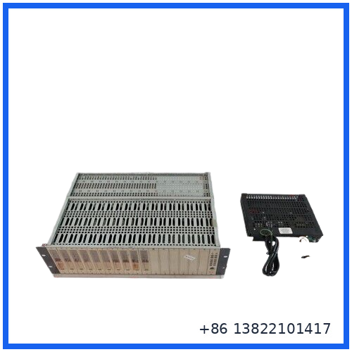
The SIEGER 05701-A-0511 is a 16-Way Rear Access Rack Assembly designed for the Sieger System 57 / 5704 gas detection and control platform.
It is a full 19-inch × 3U rack designed for rear field-wiring access. The rack provides the mechanical mounting structure, internal backplane, control-card positions, and relay-interface section required to build a System 57 control installation.
The rack uses a two-chamber construction. One chamber houses the control electronics, while the other accommodates relay interface cards. A backplane between the two sections provides the signal-routing path between the control cards and the Engineering Card. This configuration is particularly useful where field wiring needs to remain accessible from the rear of the cabinet.
The model is also associated with the 05701-A-0405 power supply assembly. Available system information identifies an 85–264 VAC input range at 47–440 Hz and a 24 VDC output configuration.
Main Features
- Sieger System 57 / 5704 rack assembly
- 16-way rear-access configuration
- Full 19-inch rack width
- 3U rack height
- Rear field-wiring access
- Separate control-card and relay-interface chambers
- Internal backplane for signal routing
- Designed for System 57 gas detection and control equipment
- Compatible with associated Sieger 5704 control cards
- Supports cabinet-level installation
- Associated power supply: 05701-A-0405
- Wide-range AC input configuration
Product Datasheet
| Parameter | Specification |
|---|---|
| Brand | SIEGER / Zellweger |
| System | System 57 / 5704 |
| Model | 05701-A-0511 |
| Product Type | 16-Way Rear Access Rack Assembly |
| Rack Configuration | Rear Access |
| Rack Width | Full 19-inch |
| Rack Height | 3U |
| Card Capacity | 16-way configuration |
| Field Wiring | Rear access |
| Internal Structure | Two separate chambers |
| Backplane | Integrated signal-routing backplane |
| Input Voltage | 85–264 VAC |
| Input Frequency | 47–440 Hz |
| DC Output | 24 VDC |
| Power Configuration | Commonly listed as 50 W; system PSU configurations may be rated higher |
| Associated PSU | 05701-A-0405 |
| Application | Gas Detection / Control System |
| Installation | 19-inch equipment cabinet |
| Rack Orientation | Rear field-wiring configuration |
The original System 57 documentation identifies 05701-A-0511 specifically as the full 19-inch wide by 3U high rack with rear field-wiring connections.
Rack Construction and Function
The 05701-A-0511 is more than a simple empty card frame.
Its internal architecture separates the control electronics from the relay interface section. This allows the system’s control cards to operate in a protected section while relay interface hardware remains available for field connections.
The backplane provides the electrical connection between the installed cards. It reduces the need for individual point-to-point wiring between cards and provides an organized path for system signals.
A simplified architecture is:
Gas Detector / Sensor → Control Card → System 57 Backplane → Relay Interface Card → External Alarm / Control Equipment
This makes the rack an important part of the overall System 57 control architecture.
Typical Applications
The 05701-A-0511 is intended for System 57 / 5704 installations used in applications such as:
- Fixed gas detection
- Toxic gas monitoring
- Flammable gas monitoring
- Industrial safety systems
- Process plant gas detection
- Oil and gas facilities
- Chemical plants
- Refineries
- Utility and power facilities
- Industrial equipment rooms
- Marine and offshore installations
The 5704 control system documentation describes the rack as the housing for control cards, Engineering Card, DC input card, key kit, and associated interconnections.
Installation & Replacement Guide
1. Verify the Rack Number
Before replacement, confirm:
- 05701-A-0511
- 16-way configuration
- Rear-access arrangement
- 19-inch × 3U dimensions
- Existing card arrangement
- Power-supply configuration
The front-access and rear-access System 57 rack versions are physically different and should not be treated as interchangeable.
2. Check Cabinet Compatibility
Confirm that the cabinet provides:
- Standard 19-inch mounting space
- Approximately 3U rack height
- Adequate rear service clearance
- Proper ventilation
- Suitable grounding
- Sufficient cable-routing space
The rear-access configuration is specifically intended for field wiring from the rear of the rack.
3. Record Existing Card Positions
Before removing an existing rack, document the installed cards and their positions.
Take photographs of:
- Card labels
- Terminal connections
- Relay wiring
- Backplane connectors
- Power connections
- Engineering Card position
- Keying arrangements
This is especially important when replacing an installed System 57 rack containing multiple configured control cards.
4. Isolate the Power
Disconnect the AC supply and follow the site’s electrical isolation procedure.
Do not remove or install cards while the rack is energized unless the original system documentation specifically permits the operation.
5. Inspect the Backplane
Check for:
- Bent contacts
- Damaged card connectors
- Loose terminals
- Corrosion
- Burn marks
- Contamination
- Cracked PCB material
- Signs of overheating
6. Install the Replacement Rack
Secure the rack firmly in the 19-inch cabinet.
Reconnect field wiring according to the original documentation and recorded wiring information. Verify polarity, terminal identification, and relay wiring before applying power.
7. Functional Verification
After installation, verify:
- DC supply voltage
- Card power status
- Engineering Card operation
- Detector inputs
- Alarm indications
- Relay outputs
- Fault indications
- External alarm interfaces
A complete functional test should be performed before returning the gas detection system to service.
Maintenance Recommendations
Rack-level faults can affect multiple control cards, so several simultaneous card problems should prompt an inspection of the common rack and power-distribution path.
Pay particular attention to:
- Backplane connectors
- Power-supply connections
- Card seating
- Relay-interface connections
- Grounding
- Cabinet temperature
- Corrosion
- Loose field wiring
- Signs of electrical overheating
If several channels show faults at the same time, do not immediately assume that all individual detector or control cards have failed.
Compatibility & Replacement Notes
The 05701-A-0511 should be matched by its complete part number and rack configuration.
System 57 documentation identifies several rack variants, including:
- 05701-A-0511 — full 19-inch × 3U, rear field wiring
- 05701-A-0501 — full 19-inch × 6U, front field wiring
- 05701-A-0512 — half 19-inch × 3U, rear field wiring
- 05701-A-0502 — half 19-inch × 6U, front field wiring
These variants have different mechanical arrangements and should not be assumed to be direct substitutes.
The associated 05701-A-0405 power supply should also be checked when replacing a complete rack assembly, particularly if the replacement includes or is supplied with the PSU.
FAQ
Q1: What is SIEGER 05701-A-0511?
It is a 16-way rear-access rack assembly for the Sieger System 57 / 5704 control system.
Q2: What is the physical rack size?
It is a full 19-inch wide × 3U high rack with rear field-wiring access.
Q3: Is this a gas detector itself?
No. It is the rack assembly that houses and interconnects the control and relay-interface cards used by the gas detection system.
Q4: What power supply is associated with this rack?
System documentation and available identification data associate the rack with the 05701-A-0405 power supply.
Q5: What is the AC input range?
The commonly listed configuration uses 85–264 VAC at 47–440 Hz.
Q6: Does 16-way mean there are 16 identical detector inputs?
No. “16-way” refers to the rack/card configuration, not 16 identical gas-detector channels.
Q7: Can the 6U front-access rack replace this model?
No direct replacement should be assumed. The 6U front-access rack has a different physical configuration and wiring arrangement.
Recommended SIEGER / System 57 Related Models
- SIEGER 05701-A-0405 Power Supply Unit
- SIEGER 05701-A-0511 16-Way Rear Access Rack
- SIEGER 05701-A-0501 16-Way Front Access Rack
- SIEGER 05701-A-0512 Half-Width Rear Access Rack
- SIEGER 05701-A-0502 Half-Width Front Access Rack
- SIEGER 05701-A-0325 Control Card
- SIEGER 05701-A-0293 Control Card
- SIEGER 05701-A-0301 Control Card
- SIEGER 05701-A-0351 Control Card
- SIEGER 05701-A-0361 Control Card
These are related System 57 components. Compatibility should be checked against the complete rack configuration and the installed 5704 control-system cards.
Inspection Before Shipment
For an industrial spare rack assembly, recommended inspection includes:
- Verify 05701-A-0511 identification
- Confirm 16-way rear-access configuration
- Check 19-inch rack dimensions
- Inspect card guides and mounting hardware
- Inspect the backplane
- Check all connectors and terminals
- Inspect relay-interface section
- Check for corrosion or contamination
- Inspect AC/DC power connections
- Verify associated PSU identification if supplied
- Photograph nameplates and board markings
- Perform appropriate continuity checks
- Record inspection results
- Use suitable protective packaging for shipment
For a replacement order, it is best to compare the existing rack’s part number, rack height, access direction, installed card positions, and power-supply configuration before dispatch.