
Description
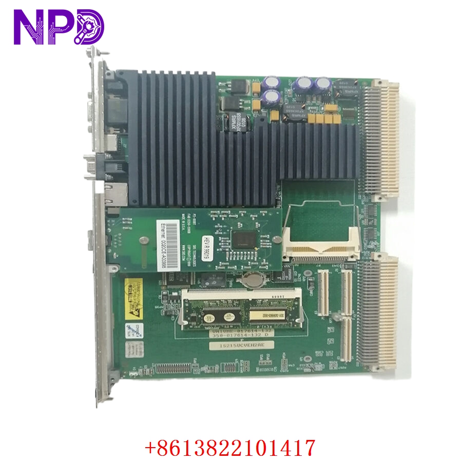
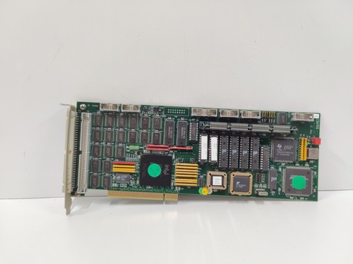
The SIMRAD TMC II PCB Card (Part No: 381-211449) is a critical electronic control module designed for Simrad marine navigation and autopilot systems. Specifically associated with the TMC (Thruster/Motor Control) series, this PCB serves as the interface between the bridge steering commands and the vessel’s propulsion or thruster actuators. It ensures responsive, accurate, and stable control of vessel movement, which is essential for maneuvering in confined port environments.
📋 Technical Specifications
🔹 Part Number: 381-211449 🔹 System Series: Simrad TMC II (Thruster/Motor Control) 🔹 Component Type: Control Logic PCB 🔹 Function: Steering/Thruster Command Processing & Actuator Feedback 🔹 Weight: Approximately 0.40 kg 🔹 Origin: Norway
🚀 Application Fields
⚡ Maritime Thruster Control Systems 🚢 Vessel Autopilot and Steering Integration ⚓ Precision Port Maneuvering ⚙️ Offshore Dynamic Positioning Systems
🛠️ Product Instructions
The 381-211449 PCB is intended for installation within the TMC II control unit cabinet. Due to the sensitive nature of the signal processing circuitry, always handle the board using anti-static protocols. Ensure the unit is mounted in a dry, vibration-dampened area of the wheelhouse or engine control room. Before insertion, verify that all backplane pins are straight and clean, and ensure the module is fully seated to maintain reliable data transmission across the ship’s control bus.
⚙️ Communication & Configuration Steps
⚙️ Address Mapping: Configuration is typically managed via internal DIP switches on the PCB or through the Simrad engineering terminal during the system’s commissioning phase. ⚙️ Station Number: The station ID is vital for ensuring the TMC II unit communicates with the correct bridge controller. Set this ID to match the vessel’s specific navigation configuration plan. ⚙️ Calibration: Calibration is performed to align the digital signal output with the physical rotation limits of the thruster/motor actuators. This is done using the built-in diagnostic menu on the bridge display.
🔋 Power-up Debugging Process
✅ Step 1: Confirm that the power supply providing 24V DC to the control cabinet is stable and free of voltage spikes. ✅ Step 2: Insert the card and power up; observe the status LEDs. A “Ready” or “Comm-Active” LED indicates that the CPU is operating and the bus link is established. ✅ Step 3: Use the navigation console to send a “Zero-set” command to verify that the thruster/actuator response is synchronized. ✅ Step 4: Perform a “Lamp and Buzzer Test” if supported by the unit to confirm that alarm reporting functionality is active.
📋 First-time Operation Checklist
✔️ Check that the part number (381-211449) matches the revision required for your specific Simrad autopilot system. ✔️ Inspect the PCB surface for any microscopic signs of salt-air corrosion or moisture damage. ✔️ Ensure that the bus cable connector is firmly attached and that the shielding is properly grounded to the ship’s common ground terminal. ✔️ Confirm that the thruster/motor feedback sensor is correctly calibrated to prevent “over-travel” alarms.
❓ Frequently Asked Questions (Q&A)
❓ Q: What does an “Alarm” light on the TMC II unit mean? 💡 A: An alarm light typically indicates a loss of feedback signal from the thruster unit, a communication timeout with the master autopilot computer, or an internal board fault. Check the communication cable continuity first.
❓ Q: Can I replace this card while the ship is at sea? 💡 A: While it is possible to replace the module, doing so will temporarily disable thruster control. Ensure the vessel is in a stable, low-traffic environment and consult the vessel’s safety manual before proceeding with any maintenance on active navigation hardware.
❓ Q: Why does the steering feel “sluggish” after replacing the PCB? 💡 A: Sluggishness often indicates that the new board requires a recalibration of the “Gain” or “Deadband” settings to match the specific inertia of your vessel’s thruster system. Re-run the calibration routine through the bridge terminal.