
Description
📝 Product Overview
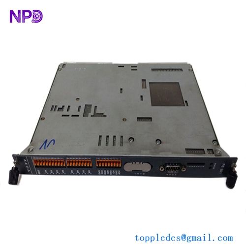
The Skipper Electronics PX-D001 is a high-performance transmitter board designed specifically for the DL850 Dual Axis Doppler Velocity Log (DVL) system. This board generates the high-power, precise acoustic pulses transmitted through the vessel’s hull transducers into the water column. By analyzing the Doppler frequency shift of the returned echoes, the system calculates highly accurate speed-over-ground and speed-through-water metrics necessary for commercial navigation and docking maneuvers.

⚙️ Technical Specifications
- 📐 Dimensions: 175 mm x 125 mm x 32 mm
- ⚖️ Weight: 0.38 kg
- 🌍 Country of Origin: Norway
🚢 Applications
- Skipper DL850 Dual Axis Doppler Velocity Log systems
- Commercial vessel speed log instrumentation racks
- Hydroacoustic signal processing and transmission networks
- Deep-water navigation and docking tracking equipment
🛠️ Usage Instructions
- Disconnect all power sources before pulling or inserting the transmitter board to prevent electrostatic discharge (ESD) or component damage.
- Perform a low-power piezoceramic transducer impedance check prior to activating full-power transmission pulses.
- Keep the board surface clean and free of dust or salt crusting; use specialized electronics cleaner if maintenance is required.
- Ensure the system configuration matching network is adjusted correctly to match the frequency rating of your installed hull transducer.
🔧 Mechanical Installation Requirements
- Fixing Method: Slides into the designated Eurocard style slot tracks within the main DL850 electronics cabinet and is secured using dual integrated front-panel captive retention screws.
- Space Clearance: Maintain the standard standard card-cage gap pitch (approx 20 mm) between adjacent boards to avoid physical contact and enable smooth removal.
- Heat Dissipation: Utilizes natural air convection inside the sealed main enclosure. Ensure the overall cabinet internal environment remains below 50°C to maximize components lifespan.
🔌 Electrical Wiring Guide
- Terminal Definitions: * Plug P1 (Backplane connector): Supply voltages (+5V, +12V, High Voltage TX Rail) and logic clock triggers.
- Coaxial SMB Terminal (TX Out): Direct high-frequency pulsed power output to the transducer selector module.
- Test Points (TP1-TP4): Internal diagnostic reference voltages and transmission pulse envelope monitoring.
- Wire Gauge: Backplane connection is pre-wired. Any auxiliary coax runs to the transducer junction box must use double-shielded RG-58 or specialized low-loss 50-ohm maritime RF coaxial cable.
- Grounding Norms: The board relies on the gold-plated grounding pads of the backplane connector. Ensure the main DL850 enclosure is bonded directly to the ship’s functional instrumentation ground bus.
📡 Communication Configuration
- IP Address: Not applicable. This board processes physical layered radio-frequency analog pulses and raw gate arrays without an on-board TCP/IP stack.
- Station ID: Hard-addressed via its physical slot destination inside the proprietary Skipper bus backplane infrastructure.
- Baud Rate: Not applicable. Operates via synchronized parallel hardware bus timing triggers and high-speed clock lines instead of serial communications strings.
❓ Frequently Asked Questions (Q&A)
- Q: Why is the speed log reporting a “Transmitter Output Low” warning?
- A: This can indicate a failure in the onboard high-voltage charging circuit, a degraded transducer element providing incorrect impedance matching, or an open circuit in the interconnecting coaxial cable.
- Q: Can the PX-D001 board be interchanged with other Skipper speed log models?
- A: No, the PX-D001 is specifically tuned to the dual-axis frequency characteristics and power profiling requirements of the DL850 series and should not be used in other models.
- Q: Is it safe to run a transmitter self-test while the vessel is in a dry dock?
- A: No, triggering high-power acoustic transmission pulses while the hull transducer is exposed to open air instead of water can permanently crack or ruin the sensitive transducer crystals due to acoustic energy reflection. Use the system’s low-voltage simulator mode instead.