
Description
◼ Product Datasheet & Technical Parameters
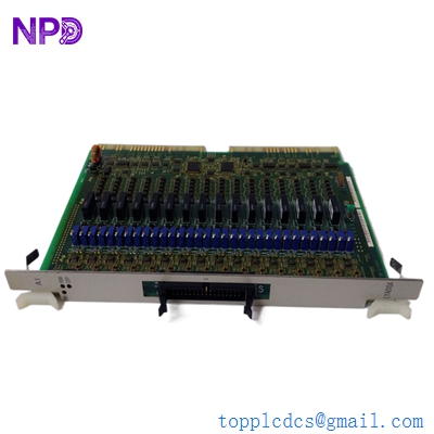
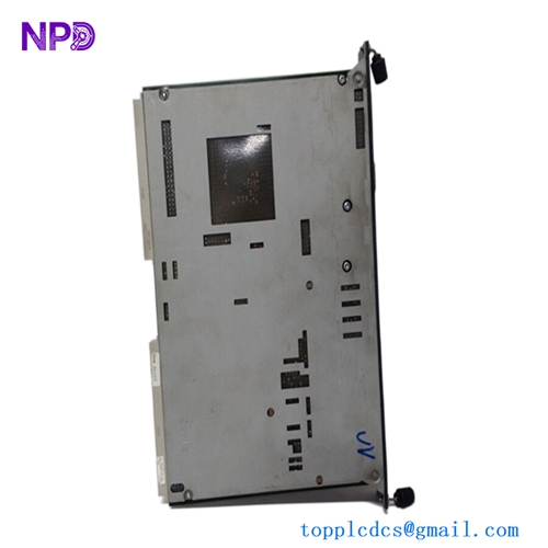
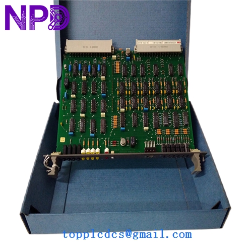
The LP339B / LP301B / LP297C designation identifies a multi-part Printed Circuit Board (PCB) set or composite controller assembly utilized within industrial and commercial-grade solar power conversion hardware.
- Type: Solar Inverter Replacement Printed Circuit Board (PCB) Assembly
- Model Codes / Sub-Designations: LP339B, LP301B, LP297C
- Physical State: Solid-State Electronic Circuit Boards (Surface Mount / Thru-hole hybrid assembly)
- Application: Power regulation, conversion management, and signal processing loops within alternative energy inverters
- Condition Formats: Frequently sourced as pre-owned, tested replacement components or specialized inventory surplus for legacy solar inverter maintenance
► Operation Specifications & Usage Methods
Proper handling and integration protocols ensure safe board replacement and stable DC-to-AC conversion restoration:
- Ensure that all high-voltage DC inputs from the solar PV array and AC grid connections are completely isolated, locked out, and discharged before opening the inverter chassis.
- Handle replacement boards strictly under ESD-safe conditions (utilizing grounded wrist straps and anti-static packaging) to protect sensitive integrated logic and switching controllers.
- Verify proper seating across internal harness connectors, ribbon cables, and mounting standoffs before re-energizing the system.
⚠ Emergency Shutdown Operation
In the event of an electrical short circuit, severe inverter fault, or facility emergency, execute the following protocol:
- Immediately open the DC disconnect switch (PV isolator) and the downstream AC circuit breaker to cut off power flow to and from the inverter.
- Allow internal high-capacity DC link capacitors adequate time to bleed down completely (typically 5 to 10 minutes) before touching internal components or circuit boards.
- Notify qualified solar service technicians and review error logs on the primary display interface before attempting any reset or hardware swap.
⚙ Troubleshooting & Common Issues
System diagnostics help isolate board-level failures within multi-card solar inverter architectures:
- If the inverter displays internal communication failures or control power loss, inspect the interconnection harnesses linking the LP-series boards to the main processing unit.
- For persistent gate-driver or power-stage faults, inspect individual components on the boards for thermal stress, discoloration, or bulging capacitors.
- Verify that firmware configurations match the operational requirements of the host inverter frame upon successful hardware replacement.
🛠 Routine Maintenance & Servicing
Preventative care ensures maximum longevity for replacement power electronics:
- Inspect internal cabinet air filters, cooling fans, and heat sink channels regularly to prevent dust accumulation and thermal degradation.
- Check internal wiring plugs and screw terminals periodically to ensure no loosening occurs due to thermal cycling or environmental vibration.
- Keep configuration data and diagnostic logs backed up to simplify future maintenance cycles.
❓ Frequently Asked Questions (Q&A)
- Q1: What specific solar inverter systems use the LP339B / LP301B / LP297C board set?
- A1: These part numbers typically serve as internal replacement control, sensing, or gate-driver boards used across specific legacy commercial or industrial solar inverter topologies.
- Q2: Are these boards hot-swappable?
- A2: No, power must be entirely shut off and DC/AC lines isolated before attempting to replace internal inverter circuit boards.
- Q3: Is post-installation calibration required?
- A3: Depending on whether the board handles voltage sensing, measurement scaling, or gate timing, zero-point calibration or firmware handshaking via the inverter’s service software may be required.