
Description
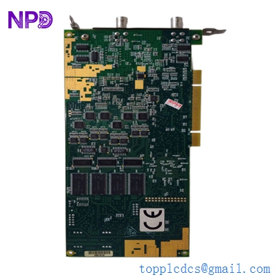
The Sperry Marine 65825812-3 is a high-reliability, marine-grade Modulator Printed Circuit Board (PCB) designed exclusively for the VisionMaster FT marine radar series. Positioned within the radar’s transceiver unit, this critical hardware component controls the precise timing, duration, and shape of the high-voltage electrical pulses delivered to the magnetron. By precisely regulating the pulse repetition frequency (PRF), it directly determines the radar’s short-, medium-, and long-range target detection profiles.

⚙️ Technical Specifications
- 📐 Dimensions: 215 mm x 160 mm x 38 mm
- ⚖️ Weight: 0.62 kg
- 🌍 Country of Origin: United Kingdom / United States
🚢 Applications
- VisionMaster FT S-band and X-band commercial marine radar transceivers
- High-power pulse-forming network (PFN) synchronization loops
- Solid-state and magnetron-based maritime navigation transmitters
- Automated target detection and anti-clutter signal shaping
🛠️ Usage Instructions
- DANGER: HIGH VOLTAGE! Never service, test, or remove the modulator board while the transceiver unit is energized. Internal capacitors retain dangerous residual electrical charges even after the primary power breaker is switched off.
- Always handle the board with a grounded anti-static wrist strap to avoid puncturing the high-sensitivity solid-state timing components through electrostatic discharge (ESD).
- Periodically check the surface of the card for heat-induced discoloration near the high-power switching transistors during scheduled dry-dock inspections.
- Ensure all high-voltage wiring harnesses and multi-pin plugs are clicked firmly into place before restoring system power.
🔧 Mechanical Installation Requirements
- Fixing Method: Slide-in chassis installation secured directly into the shielded transceiver housing tray using six M3 specialized grounding screws across the card’s perimeter.
- Space Clearance: Follow standard internal cage boundary layout rules, ensuring a minimum 15 mm air gap is maintained from adjacent high-power RF waveguide shielding plates.
- Heat Dissipation: Mounted against a structural internal aluminum heatsink plate. Ensure the thermal interface pads on the rear of the power semiconductors are intact and free of dirt to prevent thermal runaway.
🔌 Electrical Wiring Guide
- Terminal/Connector Pinouts:
- Plug J1 (Logic Interface): Low-voltage trigger signals, PRF clock synchronizations, and system monitoring telemetry.
- Plug J2 (Power Input): 48V DC / 110V DC operating rail lines from the primary radar power supply module.
- High-Voltage Output Lead: Dedicated heavy-insulated pulse-forming network (PFN) feed running directly to the magnetron cathode.
- Wire Gauge: Pre-installed factory harness connections apply. Any field repairs to the low-voltage control signal lines must use 0.5 mm² to 0.75 mm² (20–18 AWG) shielded wires, while high-voltage paths require specialty double-insulated silicone RF wiring.
- Grounding Norms: The board relies heavily on its mounting screw pads for a low-impedance ground path back to the transceiver frame. Ensure all mounting surfaces are clean, free of corrosion, and that the internal chassis ground strap is securely bonded to the ship’s radar mast frame.
📡 Communication Configuration
- IP Address: Not applicable. This board functions at the physical layered hardware level, executing raw analog signal modulation and pulse shaping without a network IP stack.
- Station ID: Hard-addressed through its physical hardwired location and interconnected bus connection within the transceiver enclosure.
- Baud Rate: Not applicable. Utilizes real-time, synchronized high-speed hardware pulse clocks running at standard multi-kilohertz PRF modes instead of serial communication lines.
❓ Frequently Asked Questions (Q&A)
- Q: What are the primary symptoms of a failing 65825812-3 Modulator PCB?
- A: Common symptoms include a sudden loss of radar video transmission, erratic target presentation profiles on specific range scales, a “Tx Trigger Fault” alarm on the bridge MFD, or the failure of the magnetron to light up entirely.
- Q: Can this modulator board be adjusted manually to fix timing issues?
- A: No. The board features factory-calibrated surface-mount components and fixed timing profiles. All pulse selection settings are managed digitally via the central processing unit and software configuration menus.
- Q: Is this card interchangeable between X-band and S-band VisionMaster FT radars?
- A: Yes, the 65825812-3 modulator design is compatible with both frequencies, provided that the transceiver software version is correctly configured to match the specific power requirements of the installed magnetron.