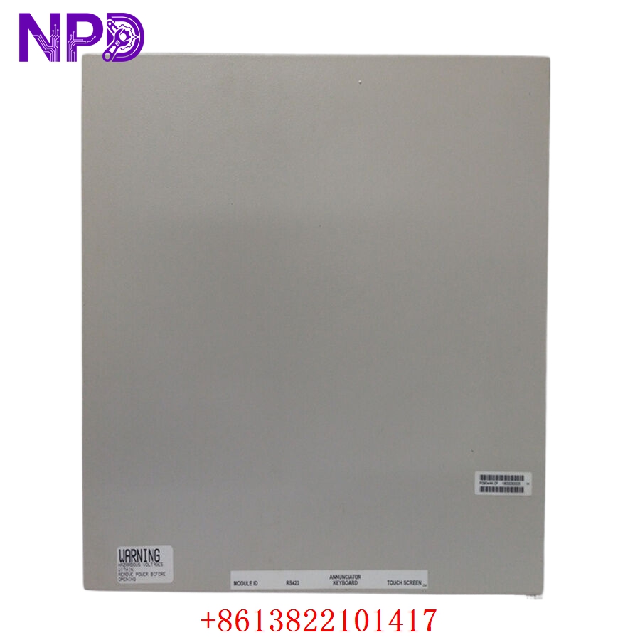

Description
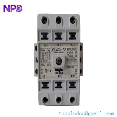
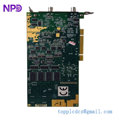
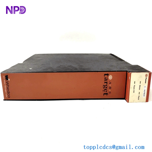
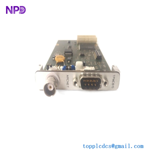
The STELLA GAMMA 064.535.493 is a comprehensive rack-mounted modular control system designed for high-precision industrial automation. This system serves as the central brain for complex machinery, integrating multiple processing and signal-handling modules into a single, unified architecture. It supports a wide array of I/O configurations, including Digital Input/Output (DI/DO), Analog Input/Output (AI/AO), and Serial I/O (SI/O), ensuring seamless data acquisition and real-time control in demanding operational environments.

Technical Specifications
| Parameter | Description |
| Model Number | 064.535.493 |
| System Family | STELLA GAMMA |
| Form Factor | Modular Rack-Mount PCB System |
| I/O Capability | DI, DO, AI, AO, SI/O |
| Weight | Varies by module population |
| Origin | European Manufacture |
Operational Guidelines & Usage
🔹 Startup Sequence
- Ensure all I/O modules are firmly seated within the backplane slots of the rack.
- Verify that field wiring terminals are secure and correctly mapped to the I/O points.
- Apply primary control voltage (24VDC or as specified by the system design) to the rack power input.
- The CPU module will perform a self-diagnostic power-on self-test (POST).
- Once the “Ready” or “Run” LED on the CPU remains solid, the system is prepared to execute control logic.
🔹 Shutdown Sequence
- Place the connected automated process into a “Safe State.”
- Disable output commands via the control software to ensure no sudden actuator movements.
- Power down the rack unit.
- Once the system is de-energized, modules can be safely accessed if necessary.
🔹 Normal Operational Flow
- The AI modules scan analog inputs from sensors at predefined intervals.
- The CPU processes these signals based on the loaded control logic (e.g., PID loops).
- The CPU updates the state of the DO modules and calculates required signals for the AO modules.
- Data is periodically logged or transmitted via the SI/O port to secondary monitoring stations.
🔹 Parameter Configuration
- Connect a programming terminal or laptop to the CPU’s communication port.
- Use the dedicated STELLA engineering software to access the hardware configuration menu.
- Define the address range and signal characteristics (e.g., 4-20mA for AO, NPN/PNP for DI) for each slot.
- Download the updated configuration to the CPU and perform a “warm” or “cold” start to apply changes.
🔹 Mode Switching
- Run Mode: Standard operational mode where the CPU executes user-defined control logic.
- Stop/Program Mode: Used for configuration updates and diagnostic monitoring. Switching is typically performed via a physical key-switch on the CPU front panel or software command.
Common Questions & Answers (Q&A)
💡 Q: What does a flashing “Fault” LED on a specific module indicate?
A: A flashing fault LED typically points to a localized issue with that module—such as an open loop on an input channel or a short circuit on a digital output. Check the wiring for that specific module first.
💡 Q: Can I replace an I/O module without shutting down the whole rack?
A: While some systems support “hot-swapping,” it is generally recommended to power down the rack to prevent electrical transients from damaging the backplane bus. Always check your specific site safety documentation.
💡 Q: How do I verify signal integrity for Analog I/O?
A: Use a calibrated multimeter to measure the loop current or voltage directly at the terminal block. Compare these readings to the values displayed in the software interface to confirm the module’s accuracy.
💡 Q: Is the system capable of network communication?
A: Yes, through the SI/O ports, the STELLA GAMMA can interface with industrial protocols (such as Modbus or proprietary fieldbus) for integration with broader plant-wide SCADA or DCS platforms.