
Description
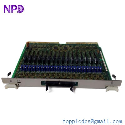
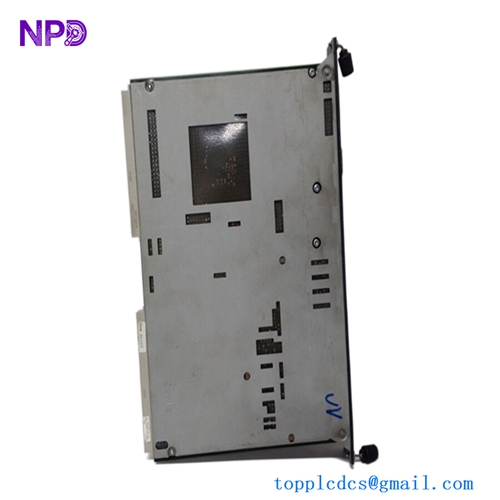
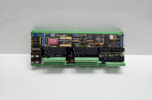
The STN Atlas DZM 402 (Part Number 271.149 289/B) is a specialized Speed Relay Module designed for critical machinery monitoring, particularly in marine propulsion and heavy industrial rotating equipment. This module functions as a safety and protection unit that monitors rotational speed (RPM) via magnetic pick-up or inductive sensors. It provides high-speed switching capabilities to trigger alarms, initiate shutdowns, or manage system interlocks when speed thresholds (overspeed or underspeed) are breached. Renowned for its precision and resilience, the DZM 402 is a staple component in legacy STN Atlas (now part of various maritime technology groups) control systems, ensuring the integrity of engine and turbine operations.
Key Technical Specifications
| Parameter | Value/Description |
| Part Number | 271.149 289/B |
| Series | DZM 402 |
| Component Type | Speed Relay / Overspeed Monitor |
| Input Signal | Inductive pick-up / Frequency pulse |
| Control Logic | Adjustable speed thresholds (Setpoints) |
| Output Type | Relay contacts (Changeover/NO/NC) |
| Operating Voltage | 24V DC (Standard industrial/marine supply) |
| Mounting | Rack/DIN-rail mount |
| Environment | Industrial/Marine (Vibration/Humidity resistant) |
| Accuracy | High-speed, low-latency threshold detection |
Recommended Related Models
These modules are frequently used within STN Atlas or associated maritime automation control cabinets:
- 271.149 289/A: Previous revision of the DZM 402 module
- 271.149 290: DZM 403 (Enhanced Speed/Directional Monitor)
- 271.149 300: Central Processor Unit for Monitoring Racks
- 271.149 310: Alarm Annunciator Module
- 271.149 350: Frequency-to-Current Converter Module
- 271.149 400: Power Supply Module for DZM Series
- 271.149 420: Input/Output Expansion Card
- 271.149 450: Relay Output Expansion Module
- 271.149 500: Logic Interface/Gate Module
- 271.149 600: Communication Gateway Interface
Important Technical Note: The DZM 402 271.149 289/B is a safety-critical device. The speed setpoints are typically adjusted via potentiometers or internal configuration jumpers. When replacing this module, it is vital to ensure the new unit’s setpoints match the original calibration values exactly to prevent unexpected engine trips or a failure to detect a true overspeed condition. Always verify the output relay configuration (normally-energized vs. normally-de-energized) matches your specific safety circuit design.