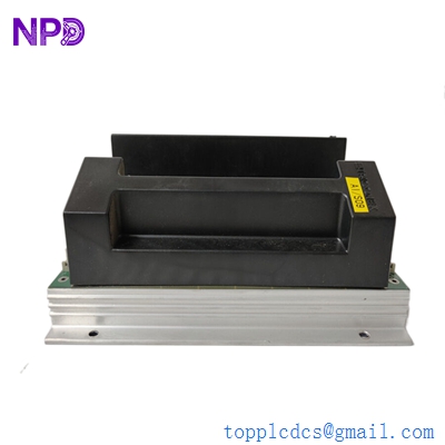

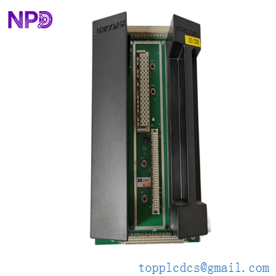
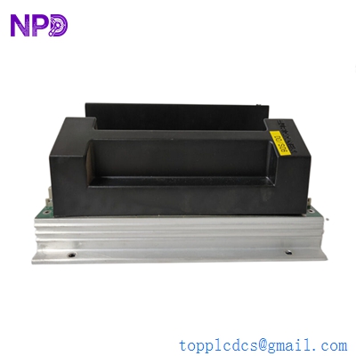
Description
- Model: 2401 (often paired with DO2401)
- Part Number: 7400209-030 (Baseplate/Module assembly)
- Brand: Triconex (Schneider Electric)
- Series: Tricon / Trident Safety Systems
- Core Function: Digital Output (DO) signal conditioning and distribution
- Product Type: Digital Output Module / Baseplate Kit
- Key Specs: 16 or 24 Channels (variant dependent) | 24 VDC | Triple Modular Redundancy (TMR)
- Voltage Rating: 24 VDC (Typical range 20–30 VDC)
- Current Rating: Up to 2 A per channel (High-current capacity for actuators)
- Response Time: < 2 ms (Essential for Emergency Shutdown)
- Isolation: 1500 VDC to 3000 VDC (Field-to-Logic isolation)
- Architecture: Triple Modular Redundant (TMR) – 2-out-of-3 voting for fault tolerance
- Diagnostics: Microprocessor-controlled self-test, loop monitoring for open/short circuits
- Safety Integrity: Certified for SIL 3 applications (IEC 61508)
- MTTF: > 100,000 years (Design life for mission-critical reliability)
- Operating Temp: -40 °C to +70 °C (-40 °F to +158 °F)
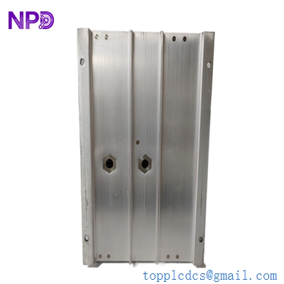
- Dimensions: approx. 10.2″ x 6.3″ x 3.1″ (Standard Tricon form factor)
TRICONEX 2401
Installation & Configuration Guide
Phase 1: Preparation (Pre-Installation)
⚠️ Safety First:
- This module is part of a Safety Instrumented System (SIS). Never replace while the process is in a hazardous state unless the loop is bypassed and a risk assessment is complete.
- Firmware Check: Verify that the hardware revision of the new 2401 matches the project configuration in the Tristation 1131 software.
- Loop Bypassing: Ensure the corresponding safety loops (e.g., ESD valves) are physically bypassed or the output is inhibited in the software to prevent accidental trips during swap-out.
Phase 2: Removal of Faulty Module
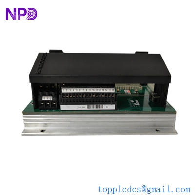
- Identification: Use the Diagnostic Monitor to identify the faulty slot. The “LOAD/FUSE” or “FIELD POWER” LED will typically be yellow on the failed unit.
- Unlocking: Loosen the top and bottom retaining screws on the module faceplate.
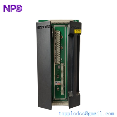
- Extraction: Use the built-in extractor handles to pull the module straight out. Avoid twisting, as this can damage the high-density backplane connector.
Phase 3: New Module Installation
- Physical Inspection: Check the 96-pin DIN connector for any bent pins or dust.
- Insertion: Slide the 2401 module into the card guides. Push firmly until it seats into the backplane.
- Locking: Tighten the faceplate screws to ensure a proper ground connection and vibration resistance.
Phase 4: Commissioning & Testing
- Self-Test: The “PASS” LED should turn solid green after the internal TMR voting logic initializes (approx. 10–30 seconds).
- Software Validation: In Tristation, verify the module status is “Active” and “Running.” Check for any “External Fault” alarms which might indicate a wiring issue with the field load.
- Functional Test: If the process allows, perform a loop test to confirm the module can successfully energize/de-energize the connected solenoid or relay.
Customer Cases & Industry Applications
Case 1: Preventing Emergency Shutdown (ESD) in an LNG Facility
Situation: A Liquefied Natural Gas (LNG) plant in Qatar identified a “Voter Mismatch” alarm on one of their Tricon racks. The 2401 Digital Output module was failing its internal diagnostics, threatening a spurious trip of a major compression train.
Task: A spurious trip would result in millions of dollars in flaring and restart costs. The plant required a replacement that was guaranteed compatible with their existing TMR architecture.
Action: We provided a New Surplus Triconex 2401 (7400209-030). Because the unit was New Surplus, it had undergone factory-equivalent testing but was available for immediate “Next Flight Out” shipping.
Result: The module was hot-swapped while the plant remained online. The TMR logic seamlessly transitioned control to the new module without interrupting the field signal. The plant manager confirmed: “The availability of this specific revision saved us a 48-hour production halt.”
Case 2: SIL 3 Compliance for a Refinery Expansion
Situation: A refinery expansion project in the USA required additional Digital Output channels for a new fire and gas detection system. They needed to maintain SIL 3 certification throughout the rack.
Task: The project engineers needed modules that were not only new but came with full traceability and documentation (COO/COC) to satisfy safety auditors.
Action: We supplied 5 units of the DO2401 with complete documentation packages. These units were sourced from a cancelled project and were still in original factory seals.
Result: The new Fire & Gas loops passed the TUV safety audit on the first attempt. The project stayed on schedule, and the refinery successfully achieved its operational safety targets.
TRICONEX 2401
Frequently Asked Questions (FAQ)
Q: What is the difference between 2401 and 2401L? A: The 2401L is a “Low Current” version designed for smaller loads, whereas the standard 2401 is built for high-current applications like driving large solenoid valves directly (up to 2 A).
Q: Can I hot-swap this module? A: Yes, Triconex systems are designed for online hot-swapping. However, the system must have at least one healthy redundant leg to maintain the output signal during the swap. Always verify your system health in the Diagnostic Monitor first.
Q: Why is “TMR” important for this module? A: TMR (Triple Modular Redundancy) means the module actually contains three independent legs. If one leg fails, the other two “outvote” it, ensuring the safety function is still performed correctly without a nuisance trip.
Q: Does it support Sequence of Events (SOE) recording? A: Yes. The 2401 supports SOE, allowing you to trace exactly when a safety trip occurred down to the millisecond, which is vital for post-incident investigations.
Q: How do I fix a “LOAD/FUSE” yellow LED? A: This usually indicates an external problem—either a blown field fuse, a broken wire to the actuator, or a short circuit in the field. Check the field wiring and the power supply to the baseplate before assuming the module is dead.