
Description
- Model: 3481
- Brand: Triconex (Invensys / Schneider Electric)
- Series: Tricon High-Density Safety Instrumented System (SIS) v10 / v11 Platform
- Core Function: Triple Modular Redundant (TMR) Pulse Input Module
- Condition: Brand New Surplus (Original authentic warehouse stock, zero run-time hours)
- Product Type: Turbomachinery Speed / Pulse Processing Card
- Key Specs: 8 Channels | 0.5 Hz to 20,000 Hz Frequency Range | Triple Modular Redundancy (3-2-0) | SIL 3 Rated
- Module Architecture: Fully Triplicated (TMR) architecture with 3 isolated internal processing channels (Legs A, B, and C). Each leg performs independent frequency-to-digital conversions on every scan before transferring data to the main processors for hardware voting.
- Channel Capacity: Features 8 independent pulse input channels. Every channel is designed to measure high-frequency periodic waveforms without missing transient speed pulses.
- Sensor Compatibility:
- Passive Magnetic Pickups (MPUs) / Variable Reluctance Sensors.
- Active Speed Sensors (Eddy Current Proximity Probes, Hall-Effect sensors requiring open-collector or active voltage pulsing).
- Frequency Measurement Range: Operating envelope from 0.5 Hz up to 20,000 Hz, optimizing the module for both low-speed turning-gear tracking and ultra-high-speed gas/steam turbine shaft monitoring.
- Input Voltage Thresholds: Configurable input sensitivity ranges capable of capturing low-amplitude signals (down to 200 mV Peak-to-Peak at lower frequencies) up to 100 V Peak-to-Peak maximum continuous overvoltage.
- Averaging & Acceleration Logic: Computes real-time acceleration, deceleration, and instantaneous rotational speed (RPM) values utilizing configurable sample window filters directly inside the module firmware.
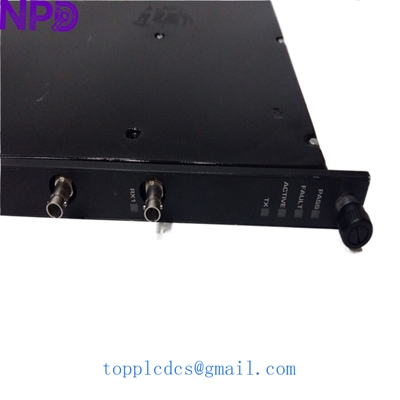
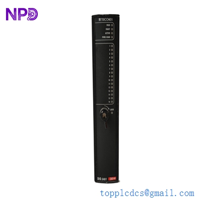
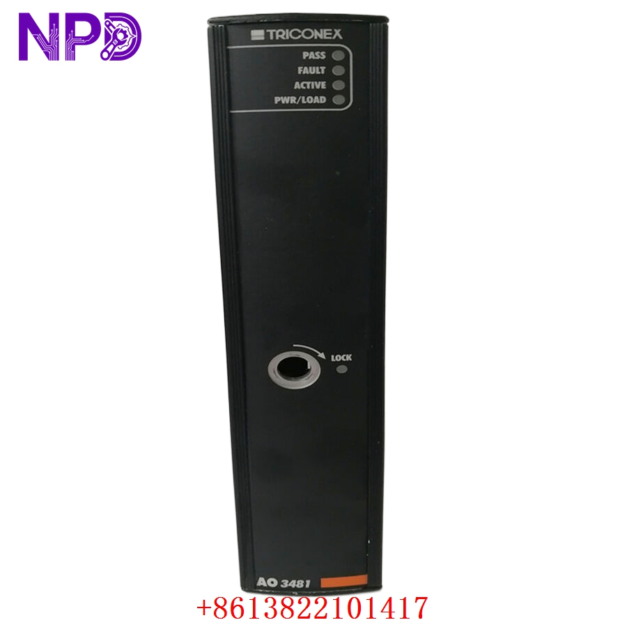
- Front Panel Array: Color-coded with a dark red/burgundy strip indicating pulse processing function. Features 4 global status LEDs (PASS, FAULT, ACTIVE, STDBY) alongside individual channel pulse indicators.
TRICONEX AO3481 3481

TRICONEX AO3481 3481
TRICONEX AO3481 3481
Installation & Configuration Guide
Phase 1: Pre-Installation (Estimated Time: 20 minutes)
⚠️ Safety Critical Warning:
- The Triconex 3481 is routinely employed as the core input module for turbomachinery overspeed protection circuits (81O). A failure to handle this module correctly can cause an uncommanded emergency trip of the turbine, resulting in severe process interruption or mechanical stress.
- Ensure you have obtained an approved maintenance bypass permit before introducing a new module or replacing an active speed monitoring slot.
Required Toolkit:
- Grounded ESD (Electrostatic Discharge) wrist strap connected to a verified earth ground point
- Precision insulated terminal driver (2.5 mm)
- High-frequency signal generator / pulse injector (e.g., Fluke 754) for bench validation
- Anti-static component transport bag
Phase 2: Removal (Estimated Time: 10 minutes)
- Verify Slot Redundancy: If you are hot-swapping a module, verify via the TriStation 1131 diagnostic panel that the targeted slot has a healthy companion module sitting in the adjacent Hot Standby (STDBY) slot. The active unit’s ACTIVE LED must be green, and the target spare’s STDBY LED should be amber.
- Loosen Captive Hardware: Using a flathead tool, completely back out the top and bottom captive locking fasteners on the module’s front bezel.
- Disengage from Backplane: Pull the upper and lower injection/extraction levers outward simultaneously to break the backplane high-density pin seal.
- Extract the Card: Slide the 3481 module straight out along the plastic guide slots. Avoid any side-to-side twisting. Place the pulled card inside an anti-static shield enclosure immediately.
Phase 3: Installation (Estimated Time: 15 minutes)
- Verify Part Alignment: Inspect the backplane edge keys on the new replacement 3481 module to ensure they align perfectly with your chassis slot layout keys.
- Slide Card into Slot: Align the circuit board borders with the chassis tracks. Slide the unit smoothly inward until the rear connectors begin to mate with the triplicated I/O backplane bus.
- Lock the Hardware Levers: Press the top and bottom extraction handles firmly inward. This mechanically pushes the module into its final seated position. Tighten the captive faceplate screws clockwise to 0.4 N·m.
Phase 4: Power-On & Loop Commissioning (Estimated Time: 35 minutes)
The Validation Protocol:
- Upon seating, the module will initialize via the chassis internal 24 V DC power bus.
- Monitor the Boot LEDs: The red FAULT LED should illuminate briefly during power-on self-tests (POST) and then turn completely off. The green PASS LED must glow solid, and if installed as a spare, the amber STDBY indicator will light up.
- Execute State Synchronization: Via the TriStation 1131 diagnostic monitor, verify that the active module is executing a background memory map synchronization onto the new module. The STDBY light will flash during this process and lock solid once complete.
- Verify Frequency Inputs: Check the real-time speed channel parameters on the HMI display. Verify that the rotational values (RPM) across all active channels track identically with zero data drops or jagged pulse variations.
- Record the installation parameters, serial number profile, and technician signatures in the facility safety system asset register.
Frequently Asked Questions (FAQ)
Q1: Can the Triconex 3481 module be hot-swapped while the turbine is running?
A: Yes, provided the system is configured with a dual-slot redundant architecture and the companion module is completely healthy (showing a solid green ACTIVE LED). When you insert the replacement 3481 into the empty standby slot, the main processors will automatically copy the runtime parameters to it. Once synchronized, it is safe to remove the older faulted module if necessary.
Q2: What types of sensors can be wired directly into the 3481 module?
A: The module is highly versatile. It interfaces natively with passive Magnetic Pickup Sensors (MPUs) which generate their own AC voltage via magnetic flux changes, as well as active sensors like proximity probes or Hall-Effect transmitters that require an external pull-up or voltage supply to generate clean, square-wave digital pulse streams.
Q3: Why does the 3481 module utilize a triplicated (TMR) processing design internally?
A: Turbomachinery speed tracking is highly safety-critical; an undetected overspeed condition can lead to turbine destruction, while a false speed reading can cause an expensive nuisance plant trip. By digitizing the speed signal across three independent processing pathways (Legs A, B, and C) and utilizing hardware voting, the 3481 eliminates single-point failures, delivering up to IEC 61508 SIL 3 safety compliance.