
Description
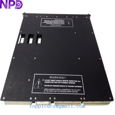
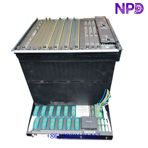
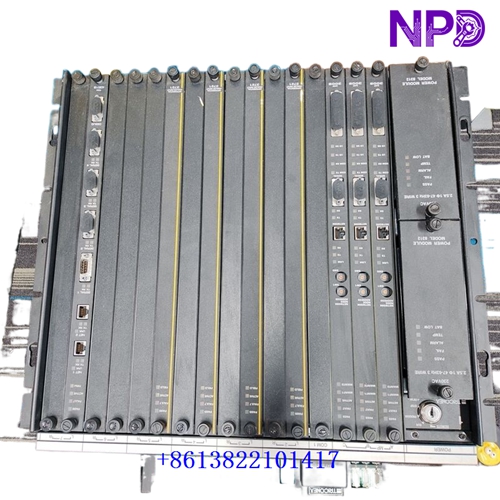
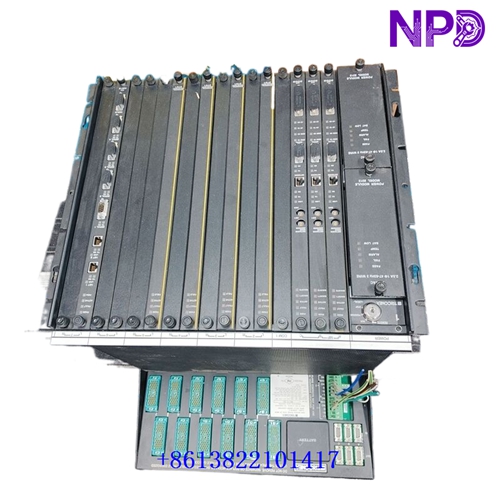
The Triconex Model 8111 is a high-density Expansion Chassis designed for use within Triconex Safety Instrumented Systems (SIS). It allows the system capacity to be scaled by housing additional I/O modules and communication modules, maintaining the strict triple-modular redundancy (TMR) architecture required for critical safety-critical applications in oil, gas, refining, and power generation.
| Parameter | Specification |
| Brand / Manufacturer | Triconex / Schneider Electric (Invensys heritage) |
| Model / Part Number | Model 8111 (Tricon Expansion Chassis) |
| Product Type | High-Density I/O and Communication Expansion Chassis |
| System Compatibility | Tricon TMR Safety Controller Systems |
| Chassis Capacity | 2 Redundant Power Modules + 8 Logical Slots for I/O and Communication modules |
| Communication Slot Limit | Communication modules are supported in designated adjacent slots of Expansion Chassis 2 (refer to system design rules) |
| I/O Bus Integration | Dual sets of triplicated RS-485 I/O bus ports (375 kb/s communication speed) |
| Distance Limitation | Total I/O Bus cable length from Main Chassis to the last expansion chassis must not exceed 100 feet (30 meters) |
| Product Status | Industrial Safety Automation Spare Part / Active Legacy Support |
First-Run Inspection Checklist
- ☑ Physical & Enclosure Integrity
Inspect the 19-inch rack-mountable metal chassis, backplane pins, power supply slots, and module guide rails for any transit damage or mechanical distortion.
- ☑ Power Module Verification
Ensure that the dual redundant power modules seated in slots A and B are correctly rated for incoming plant power and securely latched.
- ☑ I/O Bus Cabling Check
Confirm that triplicated RS-485 I/O bus cables connecting the main chassis to the Model 8111 expansion ports are correctly wired, shielded, and within the 100-foot (30-meter) total length limit.
Routine Maintenance & Servicing
- 🛠 Environmental and Thermal Management
Verify that safety instrumented system (SIS) cabinets maintain clean air filters and stable internal ambient temperatures to protect sensitive backplane components.
- 🔌 Module Slot & Connector Inspection
Periodically inspect module locking mechanisms and backplane connectors during scheduled outages to prevent vibration-induced loosening or contact oxidation.
Troubleshooting & Common Issues
- ⚠️ I/O Bus Communication Faults
If communication errors occur between the main chassis and the 8111 expansion chassis, check cable continuity, verify RS-485 bus termination, and ensure total run length does not exceed 30 meters.
- ⚠️ Power Supply Degradation
If a power module fault indicator activates on the chassis, check input supply voltages and verify redundant power sharing across both installed power units.
Safety Precautions
- 🔐 Qualified Personnel Only
Installation, rack mounting, cabling, and module replacement must be performed exclusively by certified safety system technicians trained in Triconex TMR architecture.
- ⚠️ Live System Restrictions
While Triconex architecture supports hot-swapping for many individual I/O modules under power, always follow strict plant safety protocols and check system override statuses before servicing chassis backplanes or power modules.
Frequently Asked Questions (Q&A)
- ❓ Q1: What is the primary function of the Model 8111 chassis?
A: It functions as an expansion enclosure that extends the physical capacity of a Tricon TMR safety system, providing two power slots and eight logical slots for additional I/O or communication modules.
- ❓ Q2: Can the Model 8111 be placed hundreds of feet away from the main chassis?
A: No. The Model 8111 is limited to a total I/O bus cable length of 100 feet (30 meters) from the Main Chassis. For longer distances exceeding 100 feet, a remote RXM chassis setup (such as Model 8112) must be utilized.