
Description
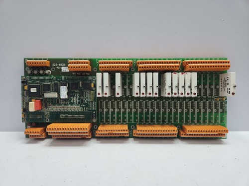
The ULSTEIN BRATTVAAG 222-652B is a critical electronic component designed for industrial maritime automation and control systems. This PCB card, identified as CAN2002B.PCB REV B, serves as a high-reliability interface module essential for the seamless communication and regulation of winches and deck machinery systems. Engineered for durability, it ensures precise signal processing and robust operational integrity in harsh offshore environments.
Technical Specifications
| Parameter | Description |
| Model | 222-652B / CAN2002B.PCB REV B |
| Manufacturer | ULSTEIN BRATTVAAG |
| Dimensions | Standard Industrial PCB Form Factor |
| Weight | Approximately 0.45 kg |
| Origin | Norway |
| Application | Marine Winch Control / Deck Machinery |
Operational Guidelines & Usage
🔹 Startup Sequence
- Ensure all physical connections are securely fastened to the card terminals.
- Verify that the primary power supply voltage matches the equipment requirements.
- Power on the main control cabinet first to stabilize the bus voltage.
- Activate the local control panel associated with the winch system.
- Monitor LED indicators on the CAN2002B card to confirm successful initialization (stable green light).
🔹 Shutdown Sequence
- Place the winch control system into “Neutral” or “Stop” mode.
- Power off the local control panel.
- De-energize the main control cabinet.
- If the system is to remain idle for an extended period, ensure the card is protected from humidity and extreme temperature fluctuations.
🔹 Normal Operational Flow
- Perform a pre-start system check via the diagnostic interface.
- Select the desired operational mode (Manual or Auto) via the operator console.
- Execute the control command. The PCB will process the input signals and modulate the hydraulic or electric actuators accordingly.
- Continuously monitor feedback signals to ensure the winch tension and speed remain within safe thresholds.
🔹 Parameter Configuration
- Access the system configuration interface using the authorized maintenance console.
- Navigate to the “Module Settings” or “I/O Configuration” menu.
- Locate the address mapping associated with the 222-652B card.
- Adjust values (e.g., threshold limits, sensor scaling) as required by system documentation.
- Save settings and perform a system reboot to apply changes.
🔹 Mode Switching
- Manual Mode: Operated directly via joystick or physical buttons on the deck console.
- Auto Mode: Controlled by the vessel’s central automation system; requires all interlocks to be clear. Use the toggle switch on the control panel to switch states; verify the status light reflects the intended mode before operation.
Common Questions & Answers (Q&A)
💡 Q: What should I do if the status LED turns red?
A: A red light typically indicates a communication loss or an internal fault. Check all CAN-bus cabling for physical damage or loose terminals. If cabling is intact, the PCB may require hardware diagnostics or replacement.
💡 Q: Can I replace the card while the system is powered?
A: No. It is strictly prohibited to remove or insert the PCB card while the system is energized. Always disconnect the power supply to prevent electrical surges and potential damage to the logic circuits.
💡 Q: Is the REV B version compatible with older REV A hardware?
A: Generally, yes, as revisions usually improve stability. However, verify the firmware compatibility on the main controller before deployment to ensure proper communication handshake.
💡 Q: How can I prevent corrosion in marine environments?
A: The card is treated with a conformal coating. To maintain longevity, ensure the control cabinet seals are intact and use anti-corrosive contact cleaner only on terminal blocks—never on the PCB surface itself.