
Description
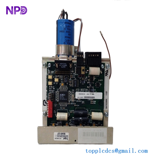
The Ulstein DC0033A is a marine-grade, high-precision stepper motor driver board engineered for specialized positioning applications within automated vessel systems, such as valve control networks, damper actuators, and dynamic monitoring systems. This heavy-duty board converts digital index pulses from a central PLC or microcontroller into precise phase currents, driving multi-phase stepper motors with smooth micro-stepping performance. Its robust architecture guarantees high torque retention and precise positioning control under constant hull vibrations and fluctuating thermal conditions.
⚙️ Technical Specifications
- 📐 Dimensions: 168 mm x 110 mm x 32 mm
- ⚖️ Weight: 0.42 kg
- 🌍 Country of Origin: Norway

🚢 Applications
- Remote-controlled hydraulic and pneumatic valve actuators
- Engine room ventilation damper positioning controls
- Specialized marine winch and tensioning instrumentation clusters
- Precision positioning mechanisms on maritime navigation consoles
🛠️ Usage Instructions
- WARNING: Never connect or disconnect the stepper motor wires while the primary 24V DC power supply is active. Doing so will create an inductive voltage arc that can instantly destroy the board’s H-bridge power transistors.
- Always apply an appropriate thermal compound or mount the board flat against a metallic chassis if running the motor continuously at its maximum current limits.
- Use the onboard miniature potentiometer or configuration jumpers to accurately set the current limit to match the rated phase current of your connected stepper motor.
- Use an anti-static wrist strap (ESD protection) when accessing the board configuration switches to prevent puncturing the internal logic controllers.
🔧 Mechanical Installation Requirements
- Fixing Method: Mounts securely onto an internal panel backplate inside a sealed junction box using four pre-drilled M4 corner mounting holes fitted with anti-vibration rubber standoffs.
- Space Clearance: Maintain a minimum clear perimeter envelope of 25 mm around the board to facilitate clean field wire dressing and allow adequate passive heat dissipation.
- Heat Dissipation: Features an integrated aluminum thermal backing plate. Ensure that the internal enclosure ambient temperature remains below 55°C to avoid automatic thermal shutdown during high-torque operational cycles.
🔌 Electrical Wiring Guide
- Terminal Definitions: * Terminals 1–2: Main Power Supply Input (24–48V DC nominal, filtered, + / -)
- Terminals 3–4: Stepper Motor Phase A Output (A+ / A-)
- Terminals 5–6: Stepper Motor Phase B Output (B+ / B-)
- Terminals 7–9: Optoisolated Logic Control Inputs (Step / Direction / Enable)
- Chassis Ground: Dedicated terminal block position bonded to the structural frame
- Wire Gauge: Use minimum 1.5 mm² (16 AWG) multi-strand copper wire for the high-current power supply and motor phase lines. For optoisolated logic lines, 0.5 mm² (20 AWG) shielded twisted pairs are sufficient.
- Grounding Norms: The field cable running to the stepper motor must be enclosed in a tinned copper shield. Clamp the shield directly to the cabinet’s EMC earth rail on the driver side to prevent the motor’s high-frequency PWM switching pulses from radiating electromagnetic interference (EMI) into nearby sensor lines.
📡 Communication Configuration
- IP Address: Not applicable. This hardware module operates at the physical device level, executing raw discrete pulse trains (Step/Direction commands) rather than network communication layer protocols.
- Station ID: Not applicable on standalone driver platforms. If an auxiliary network extension card is fitted, address indexing is handled externally.
- Baud Rate: Not applicable. The optoisolated logic inputs support high-speed hardware switching frequencies up to 200 kHz for seamless micro-step calculation and pulse synchronization.
❓ Frequently Asked Questions (Q&A)
- Q: Why is the stepper motor running excessively hot while at a complete standstill?
- A: Stepper motors naturally pull full current when holding a position. If the motor is overheating, check if the DC0033A board’s “Automatic Idle Current Reduction” jumper is enabled, which safely drops the holding current by 50% when the motor is stationary.
- Q: What does a solid red “FAULT” LED indicate on the board face?
- A: This points to an active protection trip, typically triggered by an output short-circuit between the motor phases, an over-temperature condition on the drive chips, or an over-voltage surge on the DC supply line.
- Q: Can this driver board be configured for different micro-stepping resolutions?
- A: Yes, the micro-stepping resolution (e.g., full step, half step, 1/4, 1/16) is adjusted using a series of small, on-board binary DIP switches located next to the control signal inputs. Always power down the unit before altering these switch settings.