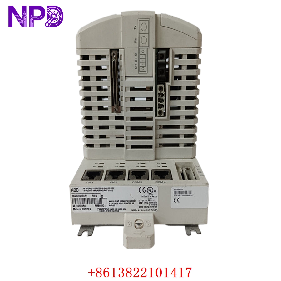

Description
The ULSTEIN TENFJORD 5880-PC1018 and 5880-PC1019 are critical interface components forming the PCB rack assembly for Tenfjord steering gear control systems. These modules act as the central logic and signal distribution hub for maritime rudder control. Engineered for reliability in the demanding conditions of marine propulsion, this rack assembly ensures precise coordination between the steering bridge commands and the hydraulic steering actuators.
⚙️ Technical Specifications
- Dimensions: 450 mm x 300 mm x 200 mm (Rack assembly)
- Weight: 3.5 kg
- Country of Origin: Norway
- Supply Voltage: 24V DC / 220V AC (Varies by power module configuration)
- Operating Temperature: -20°C to +55°C
- Housing: Ruggedized steel rack for bulkhead or cabinet mounting
🏗️ Application Areas
- Marine Steering Gear Control Systems
- Rudder Actuation and Synchronization
- Azimuth Thruster Control
- Integrated Vessel Maneuvering Systems
- Heavy-duty Hydraulic Steering Interfaces
📖 Product Usage Instructions
The PCB rack must be installed within a ventilated, vibration-isolated electrical cabinet in the steering gear room or bridge console. All signal wiring must be shielded to prevent electromagnetic interference from large shipboard motors. Ensure the backplane is clean and that the PC1018/PC1019 cards are firmly seated in their respective slots before applying system power.
🌐 Communication Configuration Steps
- IP Address: These modules primarily utilize analog and digital bus protocols; if utilizing an Ethernet gateway, configure the network via the system’s primary interface terminal.
- Station Number: Hardwired address jumpers or DIP switches on the rear of the rack assembly are used to identify the specific rack node to the main steering controller.
- Baud Rate: If connected via serial communication, verify that the baud rate matches the Tenfjord steering control standard (typically 9600 to 19200 bps).
⚡ Power-Up Debugging Flow
- Confirm main supply voltages at the rack input terminals.
- Check for the “Power OK” indicator on the front panel of the power distribution card.
- Observe the individual PCB “Heartbeat” LEDs; a steady blink indicates that the card logic is running.
- If a “Link Fault” LED is illuminated, inspect the ribbon cables connecting the PC1018/PC1019 modules to the backplane.
- Verify the output voltage to the steering gear hydraulic valves.
✅ Initial Run Checklist
- Perform a “Full Sweep” of the rudder from port to starboard to verify smooth actuation.
- Check that feedback signals from the rudder angle transmitter (RAT) align with the bridge indicators.
- Inspect all terminal block connections for thermal signs or looseness after the first 24 hours of operation.
- Document the current software/hardware revision of the installed PCB modules.
- Test the emergency manual steering bypass to ensure it overrides the rack signals correctly.
❓ Frequently Asked Questions (Q&A)
Q: What is the difference between the PC1018 and PC1019 modules? A: Typically, these represent different logic stages in the control chain—one module often handles the input signal processing (steering command), while the other handles the feedback loop and actuator output logic.
Q: Can I replace a single PCB while the system is powered? A: It is strongly recommended to isolate the power supply to the rack before removing any PCB cards to avoid voltage spikes that could damage sensitive logic components.
Q: Why does the rack show intermittent “Alarm” indicators? A: Intermittent alarms are often caused by degraded connections in the backplane or signal noise on the rudder angle feedback loop. Check for cable shield grounding issues first.
Q: Are these modules repairable? A: Due to the high-precision nature of maritime steering control, component-level repair should only be performed by authorized service partners who can recalibrate the modules after repair.