
Description
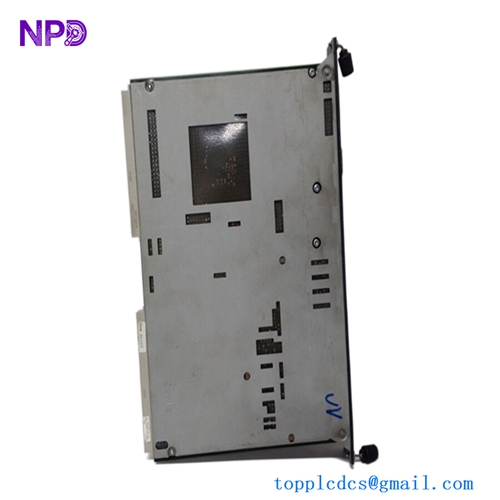
The UZUSHIO ELECTRIC UBFX1 (Part No: 1237B) is a specialized PCB control card engineered for maritime automation and electrical power systems. As a core component within the Uzushio Electric ecosystem, the 1237B provides critical logic control and signal processing functionality. It is designed to ensure stability and precision in governing the electrical distribution and machinery control processes on board large vessels.

📋 Technical Specifications
🔹 Part Number: 1237B 🔹 Model Series: UBFX1 🔹 Component Type: Control Logic PCB 🔹 Function: System Monitoring and Signal Processing 🔹 Weight: Approximately 0.35 kg 🔹 Origin: Japan
🚀 Application Fields
⚡ Marine Power Distribution Systems ⚓ Vessel Automation and Control 🏭 Industrial Logic and Relay Control ⚙️ Specialized Maritime Machinery Interfaces
🛠️ Product Instructions
The 1237B PCB is designed for installation in standard Uzushio control cabinets. Handle the board only by the edges to prevent electrostatic damage to the sensitive logic gates. Ensure the backplane interface slot is clean and devoid of dust before insertion. Secure the board firmly to ensure it remains seated despite the high-vibration environment typical of engine rooms and shipboard facilities.
⚙️ Communication & Configuration Steps
⚙️ Address Mapping: Configuration is typically managed via physical jumpers or DIP switches located on the PCB surface. Verify these match the requirements documented in your specific vessel’s wiring diagram. ⚙️ Station Number: The unit functions as a node within the local control bus; ensure the station address is correctly set to correspond with the main controller’s I/O configuration. ⚙️ Baud Rate: Communication parameters are pre-set for compatibility with Uzushio serial bus protocols. If communication errors occur, verify that the cable termination resistor is correctly installed at the end of the bus.
🔋 Power-up Debugging Process
✅ Step 1: Double-check that all field wiring connectors are fully pushed into their respective headers. ✅ Step 2: Power on the control rack and observe the “Status” LED indicator on the PCB face. ✅ Step 3: Confirm that the internal voltage regulator is outputting the correct logic-level voltage (typically 5V or 12V DC). ✅ Step 4: Utilize the central engineering workstation to perform a “System Health Check” and ensure the card is transmitting data packets successfully.
📋 First-time Operation Checklist
✔️ Confirm the part number (1237B) matches the revision of the card being replaced. ✔️ Visually inspect the board for any loose components or signs of heat stress. ✔️ Verify that the backplane pins are straight and aligned with the card’s socket. ✔️ Perform a baseline operational test of the controlled circuit (e.g., motor start/stop) in a safe, manual mode.
❓ Frequently Asked Questions (Q&A)
❓ Q: What is the most common cause of failure for the 1237B card? 💡 A: Like many maritime control cards, failure is most commonly attributed to moisture, salt-air corrosion, or long-term thermal fatigue. Regular inspections and proper cabinet ventilation are key to longevity.
❓ Q: Can I repair this board if a component fails? 💡 A: While minor repairs may be possible, it is not recommended for critical safety systems due to the complexity of multi-layer PCB traces. Replacing the unit with an original manufacturer part is the safest and most reliable approach.
❓ Q: What does it mean if the status LED is blinking rapidly? 💡 A: A rapidly blinking LED usually indicates a “Watchdog” timeout or a communication heartbeat error. This often means the card is not receiving consistent data from the main controller. Check the data bus wiring.