
Description
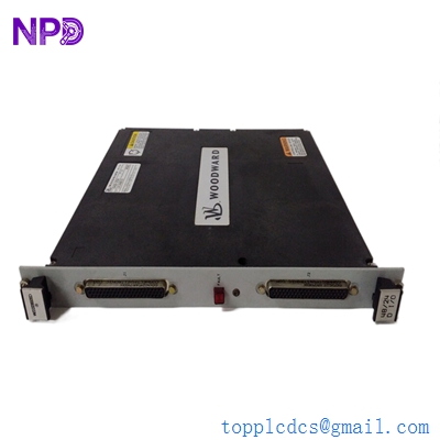
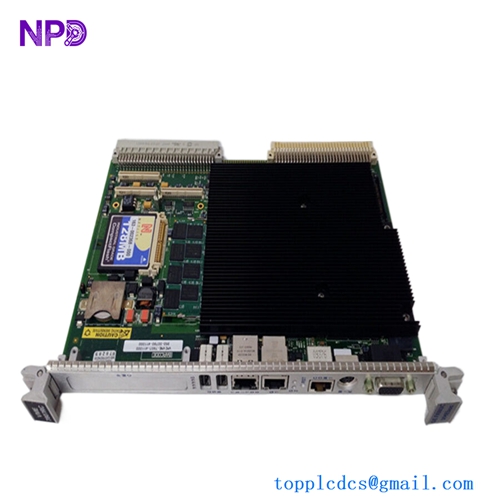
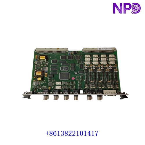
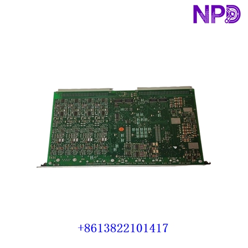
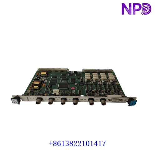
The Vibro-Meter (Meggitt) VM600 MPC4 (associated part numbers: 200-510-071-113 and 200-510-111-034) is a high-integrity, multi-channel Machinery Protection Card (MPC) engineered specifically for the VM600 rack-based safety and protection system. It functions as the core processing and data acquisition engine for critical rotating machinery protection, continuously monitoring vibration, position, and speed to execute automated machinery trips before catastrophic failure occurs.
| Parameter | Specification |
| Brand / Manufacturer | Vibro-Meter / Meggitt |
| Model / Series | VM600 Machinery Protection System (MPS) |
| Module Part Numbers | 200-510-071-113 / 200-510-111-034 |
| Product Type | Machinery Protection Card (MPC4) / Protection Module |
| System Compatibility | VM600 19-inch rack frames (ANE / ABE series racks, paired with IOC/IOCN rear interface cards) |
| Channel Capacity | 4 independent dynamic input channels (vibration, pressure, or position) + speed (tachometer) inputs |
| Processing Architecture | High-performance digital signal processing (DSP) for real-time limit checking and alarm generation |
| Relay Outputs | Integrated alarm and danger relay trip voting logic |
| Operating Temperature | 0°C to +65°C (32°F to 149°F) |
| Product Status | Industrial Safety & Machinery Protection Spare Part |
First-Run Inspection Checklist
- ☑ Physical & PCB Board Integrity
Inspect the front faceplate, status LEDs, internal multi-pin connectors, and electronic board components for any transit vibration damage or pin misalignment.
- ☑ Rack Slot Alignment & Pairing
Ensure that the MPC4 card is inserted strictly into its designated front-side protection slot on the VM600 rack and aligned correctly with its corresponding rear IOC interface module.
- ☑ Firmware & Configuration Version Match
Verify that the card’s internal configuration and firmware version match the site’s approved safety and protection software setup before putting the loop online.
Routine Maintenance & Servicing
- 🛠 Event Log & Diagnostic Monitoring
Periodically review the card’s event buffer, alarm history, and self-test diagnostic logs via the host software to catch signal degradation or hardware faults early.
- 🔌 Sensor Loop & Termination Checks
Inspect field sensor wiring terminals on the matching rear IOC modules during scheduled plant outages to verify loop integrity and shield ground continuity.
Troubleshooting & Common Issues
- ⚠️ Sensor Input Fault / Transducer Open Circuit
If a channel triggers a transducer fault LED, check field wiring continuity, verify -24 VDC sensor power supply rails, and inspect proximity probe or accelerometer gaps.
- ⚠️ Trip Relay or Alarm Latching Issues
If alarm thresholds fail to actuate protection relays, review voting logic configurations in the system software and confirm that hardware bypasses are cleared.
Safety Precautions
- 🔐 Qualified Personnel Only
Installation, parameter configuration, and hardware maintenance must be executed exclusively by certified machinery protection and vibration analysis specialists.
- ⚠️ Live Safety Loop Interlocks
Because the MPC4 card directly drives critical machine shutdown and trip loops, always review plant safety procedures, obtain proper authorizations, and engage necessary hardware/software overrides before servicing the card.
Frequently Asked Questions (Q&A)
- ❓ Q1: What is the primary function of the MPC4 card?
A: It functions as a dedicated machinery protection module, acquiring real-time vibration and position data from 4 input channels, comparing them against pre-configured danger and alert limits, and driving safety trip relays to protect turbines, compressors, and pumps.
- ❓ Q2: How does the MPC4 interface with field wiring?
A: While the MPC4 occupies the front slot of the VM600 rack to handle data processing and protection logic, all physical field transducer wires are terminated on a matching rear Input/Output Card (such as an IOC module) located directly behind it.