
Description
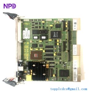
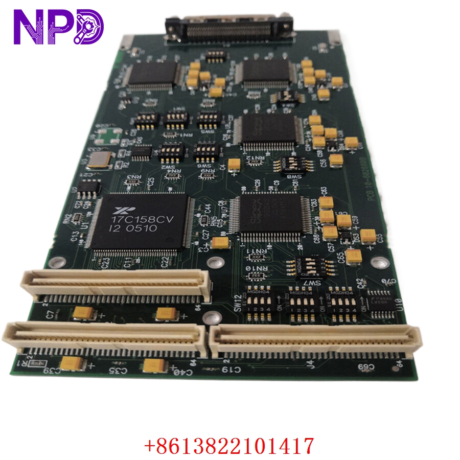
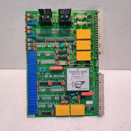
The WARTSILA LIPSTRONIC (P/N 8100224.1A, REV 1) is a dedicated Control PCB card used in the Wärtsilä Lipstronic Controllable Pitch Propeller (CPP) system. This module serves as the primary processing interface for pitch control, managing the hydraulic servo-valve signals that dictate propeller blade angle. It is vital for ensuring precise thrust control, ship maneuverability, and optimized propulsion efficiency in diverse maritime conditions.
Technical Specifications
| Parameter | Description |
| Part Number | 8100224.1A |
| Revision | REV 1 |
| Manufacturer | Wärtsilä / Lipstronic |
| Application | Controllable Pitch Propeller (CPP) Control |
| Function | Pitch Feedback & Servo-valve Signal Processing |
| Compatibility | Lipstronic Propulsion Control Systems |
| Weight | Approximately 0.45 kg |
| Origin | Finland / Global Manufacturing |
Operational Guidelines & Usage
🔹 Startup Sequence
- Ensure the control card is securely seated in the Lipstronic processor rack.
- Confirm the 24VDC system power is stable and that no alarms are present on the bridge telegraph or main control panel.
- Upon system power-up, the card performs a self-diagnostic check of the pitch feedback loops.
- Verify that the “System Ready” LED on the front panel is illuminated before attempting to engage the propeller pitch from the bridge.
🔹 Shutdown Sequence
- Set the CPP system to “Zero Pitch” (Neutral) position via the bridge lever.
- Once the propeller has reached the neutral pitch position, the system can be taken to “Standby.”
- Power down the control rack as per the ship’s electrical isolation procedures.
- If removing the card for maintenance, use an ESD-safe strap to avoid damaging the sensitive signal processors.
🔹 Normal Operational Flow
- The card receives the “Pitch Demand” signal from the bridge telegraph or propulsion control system.
- It compares this demand against the “Actual Pitch” feedback signal received from the hydraulic actuator.
- The card executes a PID control algorithm to output the precise current (mA) required to drive the hydraulic servo-valve.
- It continuously monitors the feedback loop for deviations; if the actual pitch deviates from the demand by a defined threshold, it alerts the bridge control system to prevent loss of thrust control.
🔹 Parameter Configuration
- Access the system configuration via the Wärtsilä service software interface.
- Calibrate the “Min” and “Max” pitch endpoints to ensure the physical propeller blades match the bridge indicator scale.
- Adjust PID gain parameters only if the propeller response is sluggish or hunting (oscillating) around the setpoint.
- Save the calibrated settings to the card’s non-volatile memory and perform a functional test.
🔹 Mode Switching
- Auto Mode: Standard operation where the card manages pitch based on bridge lever position.
- Manual/Emergency Mode: Bypasses the card’s automated PID control, allowing the operator to control the pitch via direct hydraulic solenoid override (typically performed at the local hydraulic power unit).
Common Questions & Answers (Q&A)
💡 Q: What should I do if the bridge indicator shows “Pitch Feedback Error”?
A: This indicates a loss of signal from the propeller hub sensor or an issue with the feedback processing on the card. Check the cabling from the propeller hub to the Lipstronic rack first. If the wiring is intact, test the feedback signal input at the terminal block to see if it remains steady.
💡 Q: Can I replace this card while the engine is running?
A: Generally, it is not recommended to pull control cards while the vessel is in maneuvering or open-sea transit mode, as this will immediately drop the propeller pitch to a default safe state (often zero thrust). Only replace in port or during an appropriate maintenance window.
💡 Q: How does the card handle hydraulic noise?
A: The card incorporates high-speed signal filtering to ignore electrical noise generated by nearby hydraulic solenoid coils. If the card begins to behave erratically, ensure the signal cables are properly shielded and grounded to the common bus.
💡 Q: What is the significance of the “REV 1” designation?
A: The revision number identifies the hardware manufacturing batch and the associated PCB layout. When ordering a spare, always match this revision number or use the part number provided in your specific ship’s Wärtsilä parts manual to ensure compatibility with your existing system bus.