
Description
📝 Product Overview
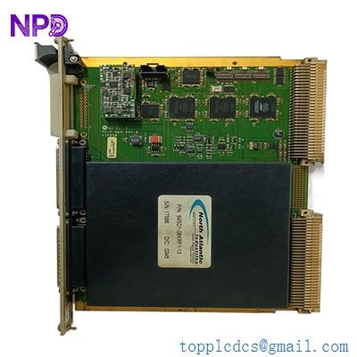
The Wartsila QLC502 is an industrial-grade Digital Control Unit (DCU) main processor and interface circuit board engineered specifically for Wartsila marine engine management and automation architectures. Operating as a decentralized processing node within the engine’s control network, the QLC502 board manages real-time data collection from various sensor arrays, processes complex closed-loop control algorithms, and drives physical actuators to regulate engine speed, cylinder lubrication, fuel injection, and safety interlocks.
⚙️ Technical Specifications
- 📐 Dimensions: 230 mm x 175 mm x 24 mm
- ⚖️ Weight: 0.78 kg
- 🌍 Country of Origin: Finland / Switzerland
🚢 Applications
- Wartsila electronic engine control systems (WECS)
- Decentralized monitoring and auxiliary pump sequencing modules
- Localized cylinder safety shutdown and alarm loop arrays
- Integrated vessel power management and engine governors
🛠️ Usage Instructions
- ESD Warning: Always wear a grounded anti-static wrist strap when handling the QLC502 card to prevent damaging the sensitive surface-mount microchips.
- Isolate all 24V DC auxiliary power distribution breakers before inserting or removing the board’s terminal headers to prevent voltage arcs.
- Use Wartsila’s official software service tool to update or match the board’s embedded flash memory firmware to your specific engine block configuration.
- Periodically inspect the multi-pin connector arrays for pin oxidation, and clean them only with a fast-evaporating electronics solvent if needed.
🔧 Mechanical Installation Requirements
- Fixing Method: Securely mounts inside the main localized engine-mounted terminal cabinet via six integrated corner screw standoffs using M4 anti-vibration locking washers.
- Space Clearance: Maintain a minimum 20 mm air boundary clearance gap from the surface of the card to any adjacent metal shielding plates or wiring trays.
- Heat Dissipation: Designed for passive convection within enclosed spaces. Ensure that external cabinet cooling vents or heatsinks are free of dirt so the ambient internal air remains below 65°C.

🔌 Electrical Wiring Guide
- Terminal/Connector Pinouts:
- Port X1 (Power): Redundant 24V DC nominal system power supply inputs (+ / -)
- Port X2 (CAN/Bus): Dual-channel isolated CAN-bus networks for inter-module synchronization
- Port X3 & X4 (I/O Array): Multi-channel analog inputs (4–20 mA / Pt100) and 24V discrete digital inputs/outputs
- Frame Grounding: Gold-plated perimeter mounting holes provide a low-resistance chassis ground trace
- Wire Gauge: Use minimum 0.5 mm² to 1.0 mm² (20–18 AWG) twisted, shielded, marine-approved multi-core cables for all data and analog telemetry paths.
- Grounding Norms: Ensure the cable shields are stripped back and securely clamped into the cabinet’s EMC grounding rails, grounding at the panel side only to eliminate destructive ground loops.
📡 Communication Configuration
- IP Address: Depending on the base application firmware profile, it hosts a static IP layout (e.g., default subnet 192.168.1.X or 10.0.0.X range) for upstream data interfacing via the module’s industrial Ethernet layer.
- Station ID: Assigned logically via a set of physical hexadecimal rotary switches located on the front edge of the board layout to establish its distinct ID node inside the local engine bus cluster.
- Baud Rate: Automatically synchronizes with the network master clock, operating at standard high-speed fieldbus rates (typically 250 kbps or 500 kbps for CANopen topologies).
❓ Frequently Asked Questions (Q&A)
- Q: What does a flashing red “SYS_ERR” LED signify on the QLC502 board?
- A: This points to a critical software watch-dog timeout, a corrupted engine configuration file in flash memory, or a mismatch in firmware revisions across adjacent modules.
- Q: Can the QLC502 board be hot-swapped while the engine control system is active?
- A: No. Hot-swapping can cause communication bus crashes on the shared network lines or trigger immediate, unexpected engine emergency shutdown safety interlocks.
- Q: What should I check if a specific sensor channel shows an “Open Loop” fault?
- A: Verify the continuity of the physical field wiring running to that specific terminal pin block, measure the 24V DC sensor excitation loop voltage, and ensure that the sensor’s current output sits within the valid 4–20 mA range.