
Description
-
-
⚙️ Product Datasheet & Technical Parameters
- Brand: WOODWARD
- Model: 8273-141
- Series: Digital Load Sharing & Speed Control Series
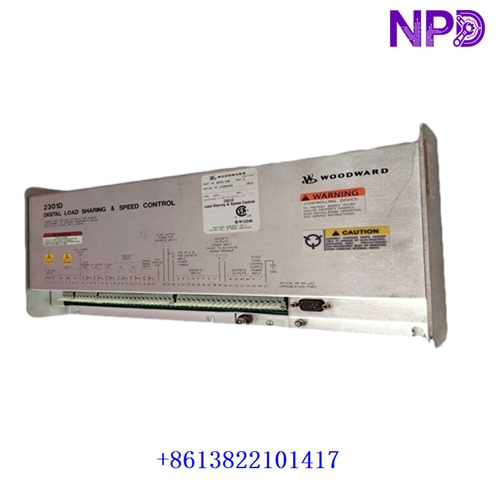
- Product Name: Digital Load Sharing / Speed Control Unit
- Place of Origin: United States
- Condition Status: Brand New / Factory Original Surplus
- Dimensions: Standard DIN-rail / Panel Mount Enclosure (Approx. 200mm x 150mm x 80mm)
- Weight: Approx. 1.8 kg
- Original Region: USA Manufacturing Plant
- Power Rating: Low-voltage electronic control circuit (External 24 VDC power supply required)
📖 Product Overview & Description
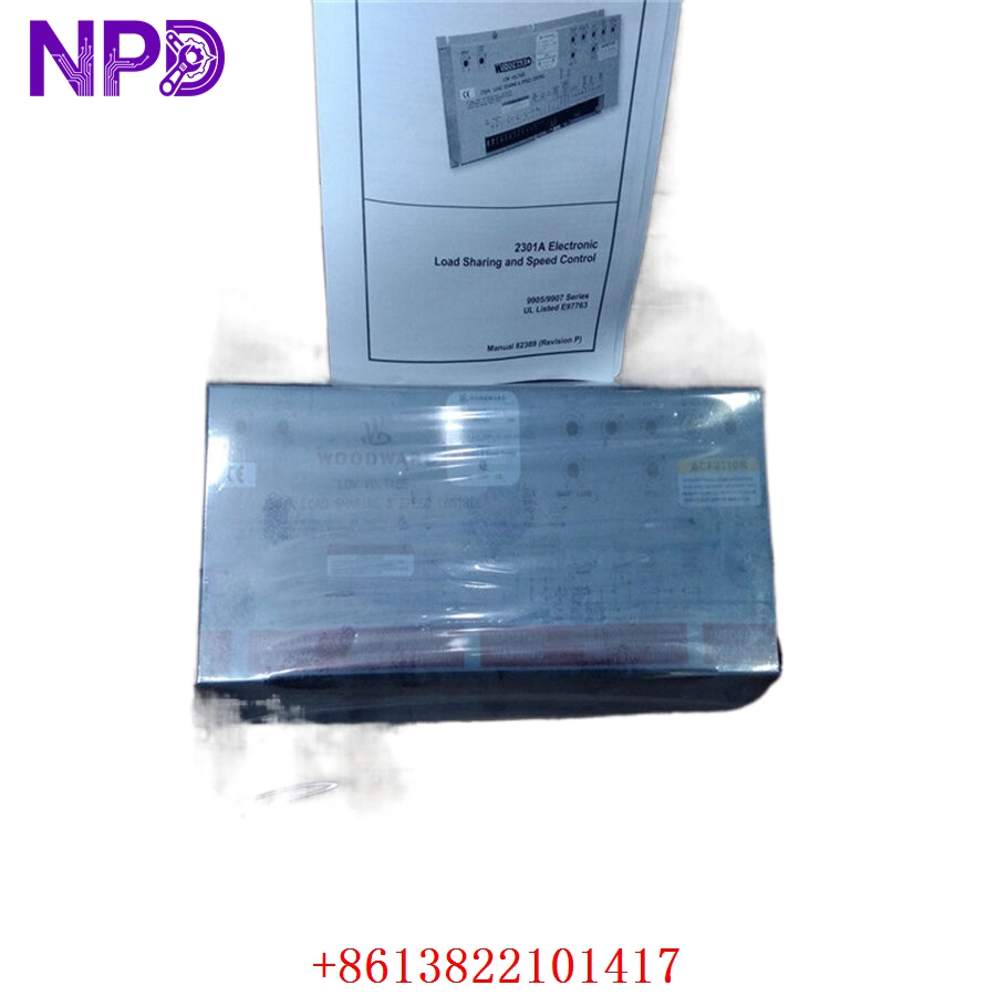
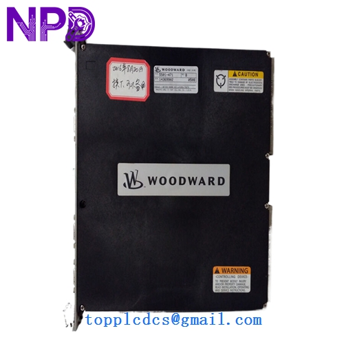
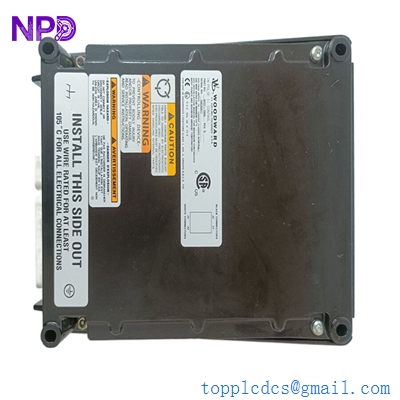
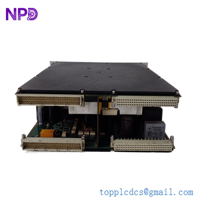
The Woodward 8273-141 is an advanced digital load sharing and speed control device engineered primarily for industrial prime movers, including diesel engines, gas engines, and small steam turbines. It delivers precise microprocessor-based speed regulation and seamless active power load sharing across multiple generator sets operating in parallel. By continuously monitoring engine speed via magnetic pickup units (MPUs) and calculating precise actuator correction signals, the unit ensures exceptional frequency stability and transient response under dynamic load fluctuations.
Built with robust industrial-grade components, the controller withstands harsh operating environments characterized by vibration, wide temperature variations, and electromagnetic interference. It features intuitive configuration software compatibility, extensive diagnostic capabilities, and failsafe protection mechanisms, making it an indispensable asset for mission-critical power generation, marine propulsion, and industrial cogeneration systems.
🛠️ Operating Specifications & Usage Methods
Proper installation and configuration are essential for achieving optimal performance from the Woodward 8273-141 control system. All electrical wiring must utilize shielded twisted-pair cables to prevent electromagnetic coupling from nearby high-voltage power lines and variable frequency drives. The unit must be securely mounted inside a vented industrial control cabinet protected from moisture, corrosive gases, and direct dust accumulation.
During initial setup, verify all sensor connections, actuator feedback loops, and communication interfaces. Configure the governing parameters—such as proportional gain, reset time, droop percentage, and speed settings—using the authorized service tool or front-panel interface in accordance with the prime mover’s specific dynamic characteristics. Always perform a cold-run verification check prior to full system synchronization.
⚡ Startup & Shutdown Sequence
Adhering to a strict startup and shutdown sequence protects the prime mover and control electronics from electrical surges and mechanical stress.
- Startup Sequence: First, inspect all mechanical linkages, fuel supply valves, and safety interlocks. Energize the auxiliary control power distribution board to supply stable 24 VDC to the 8273-141 controller. Verify that diagnostic indicators show normal status with no active error codes. Initiate the prime mover cranking cycle, allowing the engine to reach idle speed and stabilize. Once operating temperatures and oil pressures normalize, transition the unit from idle to rated operating speed. Finally, engage the load-sharing network loop before synchronizing the generator to the busbar.
- Shutdown Sequence: Begin by gradually unloading the generator through active power reduction commands until minimum load is reached. Open the main generator circuit breaker to decouple the unit from the electrical busbar. Allow the prime mover to run at no-load idle speed for thermal stabilization cooldown. Issue the stop command to shut off the fuel supply system and bring the engine to a complete standstill. Finally, de-energize the 24 VDC control power supply only after all mechanical components have fully stopped.
❓ Frequently Asked Questions (Q&A)
- Q1: What should I do if the controller displays an MPU signal loss fault?
- A1: Check the magnetic pickup sensor wiring, terminal tightness, and sensor gap distance relative to the flywheel gear teeth. Clean any metallic debris accumulated on the sensor tip and verify that signal voltage meets minimum threshold requirements during cranking.
- Q2: Can the 8273-141 operate in isolated island mode as well as parallel grid mode?
- A2: Yes. The unit supports both droop and isochronous governing modes, allowing seamless operation in single-unit island applications or multi-unit parallel load-sharing configurations.
- Q3: How do I resolve hunting or speed oscillation issues during engine operation?
- A3: Speed hunting is typically caused by excessive proportional gain or improper actuator linkage adjustment. Adjust the PID tuning parameters incrementally through the configuration software while monitoring real-time response curves, and inspect mechanical linkages for backlash or friction.
-