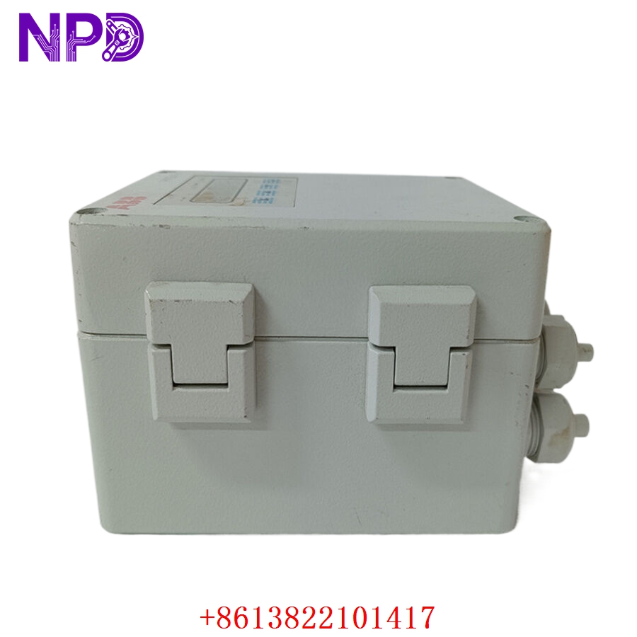

Description
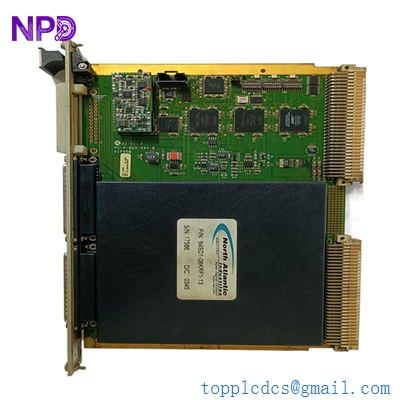
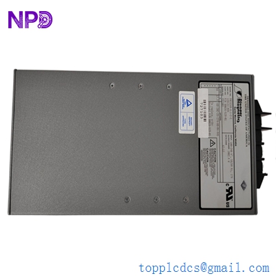
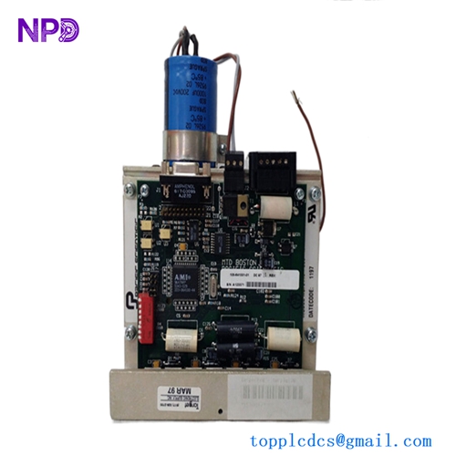
The Woodward 8290-200 is a robust, solid-state electronic speed control unit designed for precise engine governing. It serves as the primary intelligence for diesel, gas, and gasoline engines, translating speed input signals (typically from a Magnetic Pickup) into precise control signals for an electronic actuator. This ensures stable engine RPM regardless of load changes, making it a standard solution for power generation, pump drives, and compressor applications.

📋 Technical Specifications
- Model Number: 8290-200
- Series: Electronic Governor Control
- Input Signal: Magnetic Pickup (MPU) speed sensor
- Output: Proportional/Pulse Width Modulated (PWM) to actuator
- Operating Voltage: 12-32 VDC
- Dimensions: 6.5 x 5.0 x 2.0 inches (Approx.)
- Weight: 1.8 lbs (0.8 kg)
- Country of Origin: United States
⚙️ Application Areas
- Industrial Power Generation Sets
- Oil and Gas Pump Drives
- Compressor Station Engines
- Marine Auxiliary Engines
- Construction and Heavy-Duty Equipment
🛠️ Operating Instructions & Guidelines
- Installation: Mount the controller in a weather-protected control panel near the engine, ensuring it is not directly exposed to excessive heat or vibration. Use shielded cabling for the speed sensor input to prevent electrical interference.
- Environmental Requirements: Operating temperature should be maintained between -40°C and 85°C. The unit must be kept away from high-voltage cables to avoid induced noise on the sensitive speed-sensing circuit.
- Maintenance: Periodically check the magnetic pickup (MPU) air gap for metallic debris accumulation. Ensure terminal connections remain corrosion-free and tight to prevent intermittent speed fluctuations.
⚡ Power Sequence & Operation
- Power-On Sequence: 1. Ensure the DC power supply (battery/charger) is within the specified voltage range. 2. Verify all sensor and actuator wiring is secure. 3. Power up the unit; it will initiate immediately. 4. Verify that the “Ready” or “Power” LED is active (if equipped).
- Power-Off Sequence: 1. Deactivate the engine’s fuel or ignition system first to bring the engine to a stop. 2. Remove DC power from the governor control unit.
- Step-by-Step Operation: 1. Set the “Speed” (RPM) potentiometer to the required idle speed. 2. Adjust “Gain” and “Stability” (Damping) potentiometers to eliminate engine hunting under no-load conditions. 3. Apply operational load to the engine. 4. Fine-tune “Droop” if the engine is intended to be paralleled with other power sources.
❓ Frequently Asked Questions (Q&A)
- Why does the engine hunt (oscillate) at idle? This is usually caused by the “Gain” setting being too high or the “Stability” setting being incorrectly adjusted for the engine’s response time. Slowly reduce the Gain while increasing Stability until the speed settles.
- Can this governor be used with any engine? The control is highly versatile, but the actuator and MPU must be properly matched to the engine’s throttle linkage and speed range.
- What happens if the speed sensor wire breaks? The controller will detect a loss of speed signal and typically de-energize the actuator, causing the engine to shut down as a fail-safe measure.
- How do I adjust the speed remotely? The 8290-200 can often be integrated with an external 4-20mA or 0-5VDC signal interface for remote speed adjustment via a PLC or master plant controller.