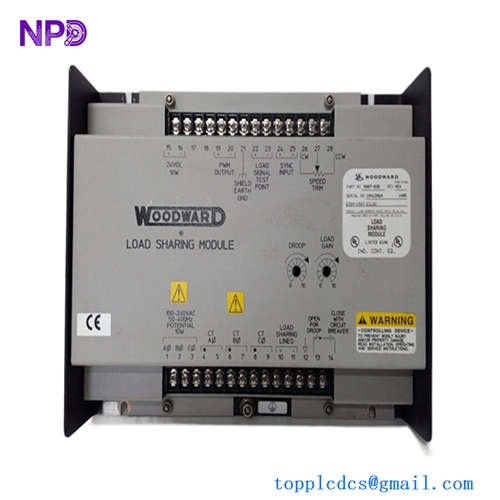


Description
- Product Parameters
- Model Designation: WOODWARD 9905-096
- Control Type: Forward Acting (Speed Control and Load Sharing)
- Input Voltage: 88–132 VAC / 90–150 VDC (High-Voltage Variant)
- Speed Range: 500 Hz to 15,000 Hz (via Magnetic Pickup)
- Magnetic Pickup (MPU): 1.0 to 30 Vrms
- Load Sharing Output: 0–6 VDC (Proportional to Engine Load)
- Actuator Output Current: 0–200 mA (Standard Output Range)
- Operating Temperature: -40°C to +85°C (-40°F to +185°F)
- Adjustment Potentiometers: Rated Speed, Idle Speed, Gain, Stability, Actuator Compensation
- Enclosure Rating: NEMA 1 Chassis (Surface Mount)
The Woodward 9905-096 is an analog electronic control device within the 2301A series designed for precise speed regulation and load sharing of diesel engines, gas engines, or steam turbines. As a forward-acting control system, it is engineered to increase its actuator output current when a speed increase is required, making it ideal for standard governors paired with fail-safe close linkages. It allows multiple parallel-connected generators to maintain proportional kilowatt load distribution across a shared utility bus while ensuring high-speed dynamic transient response.
Distinctions from Similar Models
- Action Logic: This model is Forward Acting, meaning its output current rises to open the fuel valve, distinguishing it directly from reverse-acting models like the 9907-005 which reduce output current to increase speed.
- Input Power Rating: It utilizes a high-voltage power supply interface (88–132 VAC or 90–150 VDC), whereas the 9907 series counterparts are designed exclusively for low-voltage 24 VDC industrial power loops.
- Frequency Range: Features a wide-band frequency capability (up to 15 kHz), making it compatible with a wider variety of flywheel gear teeth configurations compared to older legacy 2301 units.
Product Operation Guidelines
- Power Compatibility: Verify that the supply voltage matches the high-voltage specifications (AC or DC) before energizing to prevent immediate damage to the internal transformer and rectifier circuitry.
- Actuator Matching: Confirm the governor actuator operates on a 0–200 mA signal; if the system uses a high-current actuator, an intermediate digital or hydraulic amplifier must be installed.
- MPU Shield Grounding: Connect the Magnetic Pickup (MPU) shield to the designated chassis ground terminal only at the 2301A control end to eliminate electromagnetic interference on the speed sensing lines.
- Load Pulse Adjustment: Tune the dynamic responsiveness using the “Gain” and “Stability” potentiometers under actual operating loads; always record the original factory or baseline marks before making adjustments.