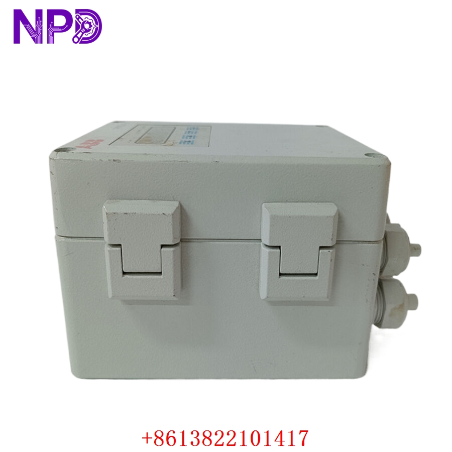

Description
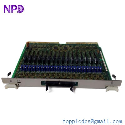
The Woodward 9905-973 is a high-performance LinkNet 8-Channel Relay Module designed for industrial control and monitoring applications. It serves as a critical interface between digital control systems and high-power field equipment, providing reliable switching and signal isolation. Engineered for robust performance in harsh environments, it is commonly utilized in power generation, turbine control, and heavy industrial automation to ensure precise execution of command signals.

📋 Technical Specifications
- Model Number: 9905-973
- Series: LinkNet
- Function: 8-Channel Relay Output Module
- Output Type: Discrete Relay Contacts
- Operating Voltage: 24 VDC (Typical)
- Dimensions: 11.25 x 5.5 x 2.25 inches (Approx.)
- Weight: 1.5 lbs (0.68 kg)
- Country of Origin: United States
⚙️ Application Areas
- Gas and Steam Turbine Control Systems
- Industrial Engine Management
- Emergency Shutdown (ESD) Systems
- Distributed I/O Control Networks
- Industrial Process Automation
🛠️ Operating Instructions & Guidelines
- Installation: Ensure the module is mounted securely on a standard DIN rail or panel surface. Verify that all wiring connections are seated firmly to prevent thermal hotspots or intermittent signaling.
- Environmental Requirements: Operate within specified ambient temperature ranges (-25°C to 70°C). Maintain a dust-free and dry installation area to avoid dielectric breakdown.
- Maintenance: Periodic inspection of relay contact wear is recommended, especially in high-cycle switching applications. Confirm the integrity of the LinkNet communication cable connections during scheduled maintenance.
⚡ Power Sequence & Operation
- Power-On Sequence: 1. Verify the 24VDC power supply is stable. 2. Connect the LinkNet communication bus cable. 3. Power up the master control system. 4. Observe the module status LEDs to confirm successful initialization and communication link establishment.
- Power-Off Sequence: 1. Command the system to a safe state (de-energize relays). 2. Disconnect the primary 24VDC power source. 3. Disconnect communication cables to prevent bus-wide errors during hardware removal.
- Step-by-Step Operation: 1. Configure the channel mapping within the Woodward control software. 2. Establish valid communication through the LinkNet network. 3. Trigger relay outputs via software commands. 4. Verify physical relay engagement through status indicators.
❓ Frequently Asked Questions (Q&A)
- How do I confirm the module is communicating with the controller? Check the onboard LED indicators. A solid green light typically confirms active power and successful communication with the host controller.
- Can I replace this module while the system is running? It is generally advised to de-energize the system before replacing hardware to prevent accidental short circuits or data corruption on the communication bus.
- What does a relay failure typically look like? Symptoms include the module failing to change state when commanded, or intermittent relay “chattering” due to contact degradation.
- Is special software required for configuration? Yes, you typically need the appropriate Woodward control software or service tool compatible with the specific turbine or engine control platform to map the I/O channels correctly.