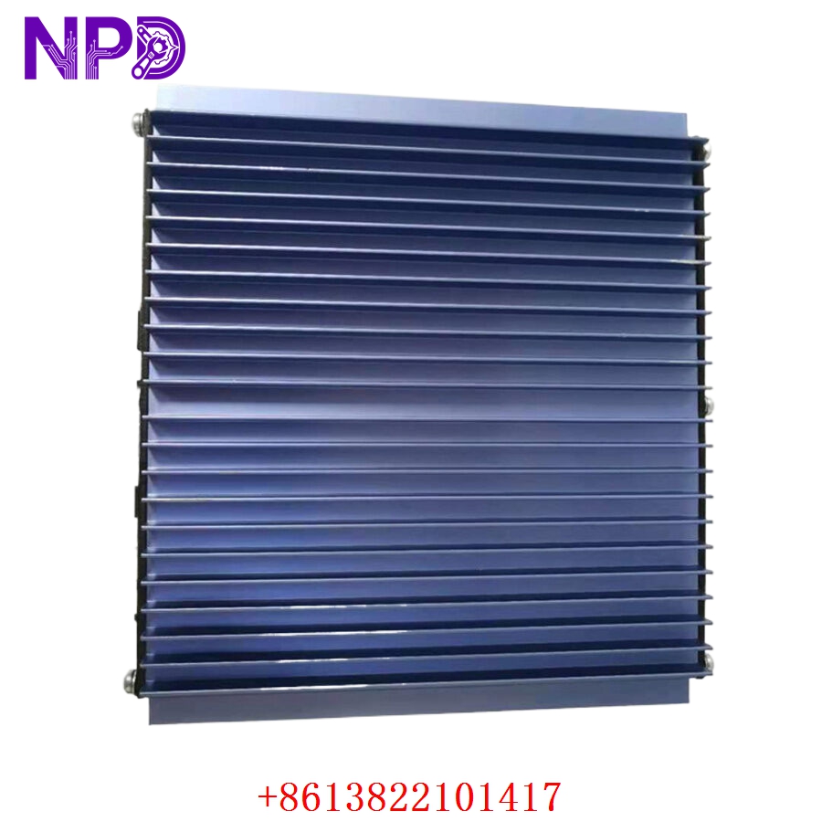

Description
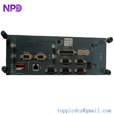
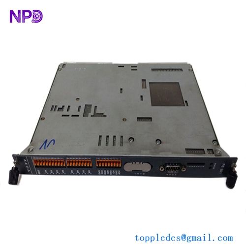
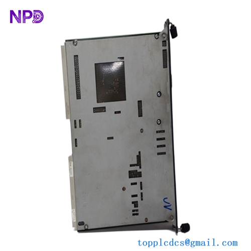
The WOODWARD 9907-838 is a precision-engineered Load Sharing Module (LSM) designed to maintain stability across parallel generator systems. This module is essential for applications requiring isochronous or droop load-sharing, ensuring that engines—particularly those using digital speed controls like Caterpillar’s PWM-based systems—operate in perfect synchronization. It acts as the backbone for reliable power distribution in demanding environments.

📋 Technical Specifications
🔹 Product ID: Woodward 9907-838 🔹 Physical Dimensions: 273.6 mm x 59.2 mm x 214.1 mm 🔹 Weight: 1.36 kg 🔹 Power Requirements: 18–32 VDC 🔹 Voltage Inputs (PT): 95–130 VAC (3-Phase) 🔹 Output Range: +0.5 to +4.5 VDC (Analog Control) 🔹 Operating Temperature: -40°C to +70°C 🔹 Origin: USA
🚀 Application Fields
⚡ Parallel Generator Operations ⚓ Maritime Power Systems 🏭 Industrial Standby Power ⚙️ Engine Governor Load Management
🛠️ Product Instructions
The 9907-838 should be mounted within a secure, vibration-damped electrical cabinet. To ensure electromagnetic compliance, strip shielded cables carefully and keep the exposed shield breakout length under 51 mm (2 inches). All wiring must be verified for correct termination before applying power. Ensure the device is isolated from the main power source during the initial mounting and wiring phase.
⚙️ Communication & Configuration Steps
⚙️ Network Identity: This unit operates on analog signal processing rather than network IP addressing. Station identity is managed through direct wiring connections between parallel units. ⚙️ Calibration: Configuration is manual, using front-panel potentiometers to define “Gain” and “Stability.” ⚙️ Signal Scaling: Adjust the load signal to match the master reference voltage—typically targeting 6 VDC at full load—using an external DC voltmeter on the designated signal terminals.
🔋 Power-up Debugging Process
✅ Step 1: Validate that all Potential Transformer (PT) and Current Transformer (CT) inputs are phased correctly. ✅ Step 2: Operate the engine in an isolated, non-paralleled state. ✅ Step 3: Apply the generator’s full load capacity. ✅ Step 4: Measure the DC output across the load signal terminals. Adjust the “Load Gain” potentiometer until the output reaches the designated 6 VDC benchmark.
📋 First-time Operation Checklist
✔️ Confirm the DC power supply remains steady between 18V and 32V. ✔️ Verify that all Current Transformers are properly loaded with their corresponding burden resistors. ✔️ Check the wiring polarity of load share lines to ensure harmonious operation across multiple modules. ✔️ Perform a vibration check to ensure the module is securely seated in its mounting rack.
❓ Frequently Asked Questions (Q&A)
❓ Q: Is this module compatible with non-Woodward controls? 💡 A: Yes, the module is specifically designed to bridge the gap between Woodward electronic governors and other digital speed controls, such as Caterpillar systems.
❓ Q: Is there any danger if I disconnect a CT while the generator is active? 💡 A: Absolutely. Disconnecting a Current Transformer while the system is under load creates a high-voltage hazard and risks damaging the device. Always ensure the system is off or the CT is shorted before maintenance.
❓ Q: What is the primary benefit of this module in my setup? 💡 A: It balances the load equally across all generators in a bank. This prevents individual units from being overloaded, optimizes engine fuel efficiency, and significantly reduces mechanical wear on the power plant.