Description
🔹 Product Overview
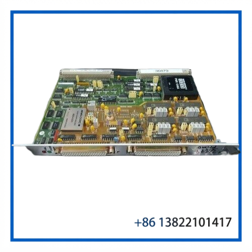
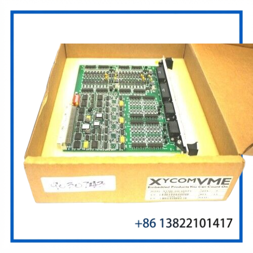
The XYCOM XVME-244 10332-00800 is a 6U VMEbus digital I/O board designed for industrial control, machine automation, and legacy computer-based control systems. The board provides 64 isolated digital I/O channels, consisting of 32 digital inputs and 32 digital outputs.
The XVME-244 uses four groups of eight channels for both inputs and outputs. Each I/O group is optically isolated from the other groups and from the VMEbus circuitry, helping separate field-level signals from the host computer backplane.
The 10332-00800 identification is associated with the Adept configuration of the XVME-244. Other board markings or assembly numbers may also appear on the PCB, so the complete board label should be checked before replacement.
⚙️ Key Features
- Brand: XYCOM
- Model: XVME-244
- Adept Part Number: 10332-00800
- Board Type: VMEbus Digital I/O Module
- Total I/O: 64 channels
- Digital Inputs: 32 channels
- Digital Outputs: 32 channels
- Input Arrangement: 4 groups × 8 channels
- Output Arrangement: 4 groups × 8 channels
- Optical Isolation: I/O groups and VMEbus interface
- Output Type: Current-sourcing outputs
- Output Supply: 10–15 VDC or 15–30 VDC, jumper selectable
- Input Voltage: Logic high 10–35 VDC; logic low −35 to 3 VDC
- VMEbus: IEEE 1014 compatible
- Form Factor: 6U double VME board
- Condition: New / Open Box
📋 Product Datasheet
| Parameter | Specification |
|---|---|
| Brand | XYCOM |
| Model | XVME-244 |
| Part Number | 10332-00800 |
| Product Name | 64-Channel Isolated Digital I/O Board |
| Product Type | VMEbus Digital I/O Module |
| I/O Configuration | 32 DI + 32 DO |
| Isolation | 300 VDC group-to-group; 1000 VDC group-to-VMEbus |
| Output Supply | 10–15 VDC / 15–30 VDC, jumper selectable |
| Output Current | Up to 400 mA per channel |
| Input Range | −35 to +35 VDC |
| VMEbus Format | A16:D16/D08 DTB Slave |
| Dimensions | Approx. 233.7 × 160 mm board format |
| Power | +5 VDC, approximately 1.0 A typical / 1.2 A maximum |
| Condition | New / Open Box |
🔌 Digital Input Architecture
The XVME-244 provides 32 digital input channels divided into four isolated groups.
The inputs are suitable for industrial discrete signals such as:
- Limit switches
- Proximity switches
- Photoelectric sensors
- Machine status contacts
- Alarm signals
- Auxiliary equipment status
- Digital interlock signals
The input circuitry accepts a broad DC signal range. A typical logic-high condition is 10–35 VDC, while a logic-low condition is −35 to 3 VDC.
Input filtering and debounce circuitry help prevent short-duration switching noise from being interpreted as repeated state changes. The specified maximum input frequency is approximately 2.8 kHz.
⚡ Digital Output Architecture
The 32 digital outputs are arranged in four groups of eight and use current-sourcing output circuitry.
The output supply voltage can be configured for either:
- 10–15 VDC
- 15–30 VDC
The output groups use jumper-selectable supply configuration, so the jumper positions should be checked before commissioning a replacement board.
Each output can provide up to approximately 400 mA under the specified conditions. Reverse-voltage protection and transient suppression are provided for the output circuitry.
Typical loads include:
- Control valves
- Relay interfaces
- Solenoid interface circuits
- Indicator devices
- Machine actuators
- Industrial control relays
External load requirements must remain within the board’s specified voltage and current limits.
🖥️ VMEbus Integration
The XVME-244 operates as a VMEbus slave module and communicates with the host processor through the VME backplane.
A typical architecture is:
Field Sensors → XVME-244 Digital Inputs → VMEbus CPU → Control Software
and:
VMEbus CPU → XVME-244 Digital Outputs → Relay / Valve / Actuator
The board supports VMEbus A16 addressing with D16/D08 data transfers. Software reads the input registers and writes to the output registers according to the host system’s I/O driver architecture.
When replacing an existing board, the VME address, jumper configuration, software driver and I/O mapping should be compared with the original installation.
🏭 Typical Applications
The XVME-244 is suitable for maintenance and replacement applications involving legacy VME-based automation systems.
Typical uses include:
- Industrial machine control
- Semiconductor manufacturing equipment
- Adept robotic systems
- Factory automation
- Process equipment
- Material-handling equipment
- Discrete signal monitoring
- Machine interlocks
- Alarm monitoring
- Legacy VME computer systems
Its combination of isolated digital inputs and outputs allows one board to handle both machine-status acquisition and actuator control.
🛡️ Isolation & Electrical Protection
Isolation is an important characteristic of the XVME-244.
The documented architecture provides isolation between I/O groups and between the field I/O circuitry and VMEbus circuitry. This helps prevent field-side electrical disturbances from directly propagating into the VME computer system.
Before installation, verify:
- Field supply voltage
- Output group jumper positions
- Input signal polarity
- Common/reference wiring
- Load current
- VME address configuration
- External connector wiring
Do not assume that the field wiring of another digital I/O board is directly interchangeable with the XVME-244.
🔧 Installation & Maintenance
Recommended Installation Procedure
- Record the original XVME board model and revision.
- Record all jumper positions before removing the old board.
- Shut down the host equipment using the approved machine procedure.
- Remove VMEbus power.
- Allow the system to discharge before handling the PCB.
- Inspect the VME backplane connector and card guides.
- Install the XVME-244 carefully into the correct VME slot.
- Verify all field wiring and connector orientation.
- Confirm output-group supply jumper settings.
- Restore power and check VMEbus communication.
- Test digital inputs individually.
- Test digital outputs with appropriate loads.
- Record the final board configuration and test results.
Use appropriate ESD precautions when handling the PCB, particularly during maintenance of semiconductor and precision automation equipment.
🛠️ Troubleshooting Guide
Board does not communicate with the host
Check VMEbus seating, slot position, address configuration, backplane condition and host software configuration.
All inputs remain OFF
Check the external input supply, common connections and field wiring. Confirm that the applied voltage reaches the specified logic-high range.
One input remains ON
Inspect the corresponding field device and wiring for a short or incorrect reference connection. If the field wiring is correct, compare the channel with another known-good input.
Outputs do not energize
Check the output-group supply voltage and jumper selection. Verify that the host software is writing to the correct output register.
Output voltage is incorrect
Verify the selected output supply range and external supply wiring. Do not exceed the specified output voltage range.
Output works without a load but fails under load
Check load current, wiring resistance and the external supply. A load approaching or exceeding the channel rating can cause improper operation.
Intermittent I/O operation
Inspect the VME connector, field terminals, grounding, shielding and external power supply. Also check for excessive temperature or contamination around the board.
❓ FAQ
Q: What is the XVME-244?
A: It is a 64-channel isolated VMEbus digital I/O module providing 32 digital inputs and 32 digital outputs.
Q: What is 10332-00800?
A: 10332-00800 is the Adept part number associated with the XVME-244 configuration.
Q: Are all 64 channels inputs?
A: No. The standard XVME-244 configuration provides 32 inputs and 32 outputs.
Q: Are the digital inputs isolated?
A: Yes. The I/O is arranged into isolated groups, with isolation between I/O groups and the VMEbus circuitry.
Q: What voltage can the outputs use?
A: The output supply range is jumper selectable between 10–15 VDC and 15–30 VDC.
Q: What type of output does the XVME-244 use?
A: The outputs are current-sourcing digital outputs.
Q: Can the XVME-244 be used as a replacement board?
A: Yes, when the host system is designed for the XVME-244 configuration. Match the model, part number, revision, jumper settings, I/O wiring and software configuration before installation.
Q: Is the 10332-00800 board new?
A: The supplied listing identifies the unit as New / Open Box. Actual packaging and included accessories should be verified before purchase.
Q: What VME format does the board use?
A: It is a 6U double-width VMEbus board with an approximately 233.7 × 160 mm form factor.
🔗 Recommended Related XYCOM Models
- XYCOM XVME-244 – 64-Channel Isolated Digital I/O Module
- XYCOM XVME-240 – VME Digital I/O Module
- XYCOM XVME-212 – VME Digital Input Module
- XYCOM XVME-214 – Digital I/O Module
- XYCOM XVME-220 – VME Digital Output Module
- XYCOM XVME-230 – VME Analog Output Module
- XYCOM XVME-240A – Digital I/O Module
- XYCOM XVME-500 – VME Analog Input Module
- XYCOM XVME-560 – VME A/D Analog Input Module
- XYCOM XVME-530 – VME Analog Output Module
📦 Spare-Part Recommendation
For legacy Adept and XYCOM VME systems, the XVME-244 10332-00800 should be purchased as a configuration-specific replacement rather than treated as a generic digital I/O card.
Before ordering, compare the XVME-244 model, 10332-00800 part number, PCB revision, VME address settings, jumper configuration, field connector arrangement and host software I/O mapping with the installed board.
For critical production equipment, maintaining a tested spare can shorten recovery time when a digital input/output channel or the VME interface develops a fault.