
Description
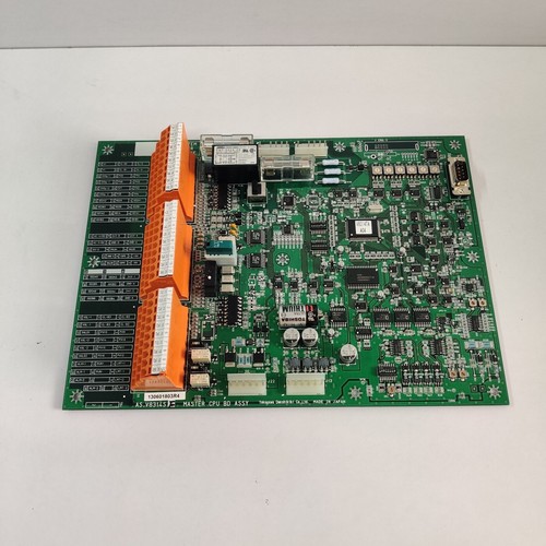
The YOKOGAWA DENSHIKIKI AS.V8314S (often referred to as an “F Master CPU Board Assembly”) is a high-performance central processing unit module designed for Yokogawa’s maritime and industrial control systems. Engineered for mission-critical reliability, this board acts as the “brain” of the control unit, executing complex logic, managing I/O data processing, and maintaining system synchronization in demanding operational environments.
📋 Technical Specifications
🔹 Part Number: AS.V8314S 🔹 Component Type: Master CPU Board Assembly 🔹 Series: Yokogawa Denshikiki Marine/Industrial Automation 🔹 Function: Centralized Logic Control / System Master Processing 🔹 Weight: Approximately 0.65 kg 🔹 Origin: Japan
🚀 Application Fields
⚡ Marine Navigation and Automation Systems ⚓ Shipboard Propulsion and Steering Control 🏭 Industrial Process Logic Supervision ⚙️ Large-scale Machinery Automation
🛠️ Product Instructions
The AS.V8314S CPU assembly is designed for installation in specialized Yokogawa control racks. Always use an anti-static wrist strap when handling the assembly to protect the highly integrated CPU and memory components. When inserting the board, ensure the edge connector aligns perfectly with the backplane slot. Secure the front mounting screws to maintain grounding contact and prevent the board from vibrating loose during high-intensity equipment operation.
⚙️ Communication & Configuration Steps
⚙️ Address Mapping: Configuration is typically managed through the system’s primary engineering software. Addresses are often assigned via the rack position and validated during the “Auto-Scan” of the control network. ⚙️ Station Number: The station identifier is stored in the board’s non-volatile memory or set via internal firmware configuration, ensuring the master controller is uniquely identified on the process bus. ⚙️ Baud Rate: Communication speed is factory-optimized for the specific Yokogawa proprietary bus. Ensure that all bus termination resistors are checked if this CPU is the primary controller at the end of the communication chain.
🔋 Power-up Debugging Process
✅ Step 1: Verify the stability of the 5V/24V logic power rails provided by the rack’s power supply. ✅ Step 2: Insert the assembly and apply power; observe the front-panel “RUN” and “SYS OK” indicators. ✅ Step 3: Wait for the initialization sequence (boot-up) to finish, indicated by the stabilization of status LEDs. ✅ Step 4: Connect the engineering console to the maintenance port to verify that the board is communicating with the peripheral I/O cards.
📋 First-time Operation Checklist
✔️ Check that the firmware version is compatible with the existing Yokogawa control system software. ✔️ Verify that the board is clean and free of dust, moisture, or oxidation on the gold-plated contact fingers. ✔️ Ensure the rack environment is within the recommended thermal operating range to prevent CPU throttling. ✔️ Perform a functional test of a basic logic loop to ensure the CPU is successfully executing commands.
❓ Frequently Asked Questions (Q&A)
❓ Q: What does a red “CPU ERROR” LED signify? 💡 A: A red error LED typically points to a self-test failure, memory corruption, or an internal watchdog timeout. Try a power-cycle first; if the error persists, the board may require a firmware re-flash or factory service.
❓ Q: Can I replace this module without losing the logic program? 💡 A: If your system uses a backup memory module (EEPROM or Battery-Backed RAM), the logic may be retained. However, always have a current backup of your project file on a laptop before replacing the master CPU.
❓ Q: Why does the system report a “Time-Out” communication error? 💡 A: Time-outs usually stem from bus contention or poor physical connection. Ensure the backplane pins are straight and the communication cable shielding is properly terminated to ground.