
Description
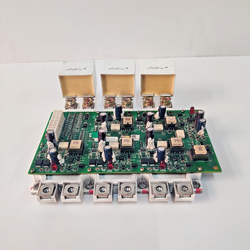
The YORK JOHNSON CONTROLS 031-02061-001 is a high-precision IGBT (Insulated Gate Bipolar Transistor) control gate driver board designed for industrial HVAC chiller systems. This board acts as a critical interface between the chiller’s main control logic and the high-power inverter modules that drive the compressor motors. By providing isolated, high-speed switching pulses, it ensures the precise regulation of motor frequency and voltage, thereby optimizing cooling efficiency and protecting power electronics from switching transients.
Technical Specifications
| Parameter | Description |
| Model | 031-02061-001 |
| Manufacturer | YORK / JOHNSON CONTROLS |
| Function | IGBT Gate Drive / Inverter Control |
| Compatibility | YORK Chiller Variable Speed Drives (VSD) |
| PCB Features | Opto-isolated high-speed signal paths |
| Weight | Approximately 0.45 kg |
| Origin | USA |
Operational Guidelines & Usage
🔹 Startup Sequence
- Ensure the board is firmly seated in the drive assembly and that the gate drive ribbon cables are securely latched.
- Verify that all DC bus power connections to the IGBT modules are tightened to the torque specifications provided in the chiller manual.
- Power on the chiller’s control voltage supply (24VDC/control transformer).
- Perform a system self-test via the chiller’s HMI. The gate driver board should be recognized, and no “Gate Drive Fault” alarms should be present.
- Initiate compressor start; the board will begin providing switching pulses to the IGBT modules to ramp up motor speed.
🔹 Shutdown Sequence
- Execute a controlled “Stop” command from the chiller keypad to allow the drive to ramp down the motor frequency.
- Wait for the DC bus capacitors to fully discharge (refer to the unit’s specific manual for the safe wait time, usually 15-30 minutes).
- Once the bus voltage is confirmed to be at safe levels, de-energize the main power feed.
- Always wear insulated gloves and use an ESD-safe wrist strap before performing any physical maintenance on the board.
🔹 Normal Operational Flow
- The board receives low-voltage pulse-width modulation (PWM) signals from the drive’s logic processor.
- It amplifies these signals to the required gate-source voltage (Vge) to turn the IGBTs on and off at high frequencies.
- It monitors the IGBT status for desaturation or fault conditions, reporting back to the drive logic in real-time.
- The board maintains precise synchronization between phases to ensure smooth motor rotation and minimal harmonics.
🔹 Parameter Configuration
- This module is typically factory-configured for specific drive ratings.
- In most field replacement scenarios, the board is “plug-and-play” regarding hardware; however, drive-specific timing parameters must be verified in the chiller’s software configuration menu.
- No physical adjustments (like potentiometers) should be made to the board unless specifically directed by technical service bulletins.
🔹 Mode Switching
- Active Drive Mode: The board is receiving command signals and switching the IGBTs.
- Standby/Fault Mode: The board is energized but inhibits switching. This state is triggered by a fault detection (e.g., overcurrent) or a “Stop” command, ensuring the IGBTs remain in a safe, non-conducting state.
Common Questions & Answers (Q&A)
💡 Q: Why does the drive display a “Gate Drive Fault”?
A: This fault indicates that the board has detected an anomaly in one of the IGBT phases, such as a short circuit, an open gate, or an under-voltage condition on the gate driver power supply. Check the ribbon cables for loose connections and inspect the IGBT modules for signs of failure.
💡 Q: Is this board sensitive to static electricity?
A: Yes, highly. The gate driver circuits contain sensitive optocouplers and ICs that can be permanently damaged by static discharge. Always keep the board in its anti-static packaging until the moment of installation.
💡 Q: Can I repair a damaged gate driver board?
A: Field repair is strongly discouraged. Because the board controls high-voltage/high-current power switches, any subtle component drift or poor solder joint can cause catastrophic failure of the expensive IGBT modules. Replace the board with a new, factory-tested unit.
💡 Q: How can I prevent premature failure of the board?
A: The most common killers are heat and moisture. Ensure the chiller’s control cabinet air filters are clean and that the cabinet cooling fans are operational. Additionally, ensure the cabinet seals are intact to prevent condensation during shutdown periods.