
Description
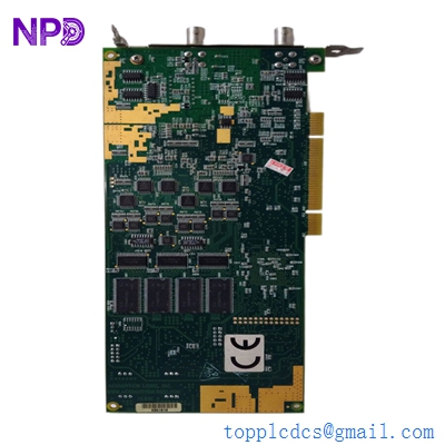
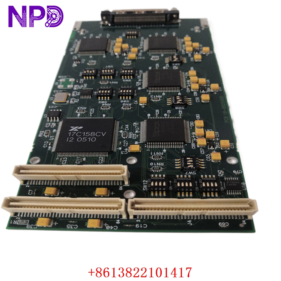
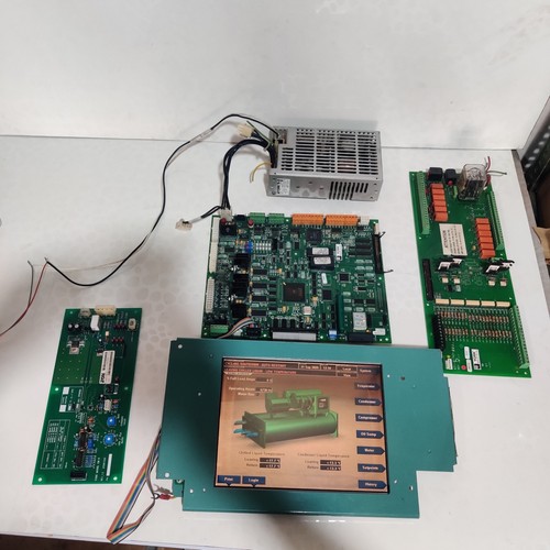
The YORK OPTIVIEW Control Center (specifically components 031-02430-000 REV E, 025-34111-000, and 031-01774-000) serves as the primary intelligence hub for high-capacity industrial chillers. This advanced human-machine interface (HMI) and controller manages every aspect of the refrigeration cycle, including setpoint regulation, compressor sequencing, safety monitoring, and energy optimization. By integrating sophisticated logic into a centralized display, it allows operators to manage complex environmental cooling systems with precision and reliability.
Technical Specifications
| Parameter | Description |
| Primary Model | OptiView Control Center |
| Part Numbers | 031-02430-000 (REV E) / 025-34111-000 / 031-01774-000 |
| Manufacturer | YORK / JOHNSON CONTROLS |
| Application | Industrial Chiller Management |
| Interface | Touch-screen/Keypad HMI with Processing Unit |
| Operating Temp | 0°C to 50°C |
| Origin | USA |
Operational Guidelines & Usage
🔹 Startup Sequence
- Ensure the chiller’s main circuit breaker is closed and control power (115V/230V) is supplied.
- The OptiView unit will boot up; wait for the splash screen to transition to the main status overview.
- Verify that there are no active “Critical” or “Safety” alarms on the dashboard.
- Set the desired “Leaving Chilled Liquid Temperature” setpoint.
- Press the “System Start” button. The controller will initiate the lubrication and startup sequence.
🔹 Shutdown Sequence
- Navigate to the “System Status” menu on the interface.
- Select “System Stop.” The OptiView will unload the compressor and execute a staged shutdown to prevent surge or mechanical stress.
- Wait for the system to reach a “Ready to Start” or “Off” state.
- If performing maintenance, open the main isolation disconnects to ensure zero energy state.
🔹 Normal Operational Flow
- The OptiView continuously monitors pressure, temperature, and current sensors throughout the chiller.
- It processes this data against internal PID loops to adjust guide vanes or motor speed.
- The display provides real-time trends, allowing operators to monitor performance efficiency.
- In the event of a variance, the controller logs the event and modulates the chiller to maintain safety boundaries.
🔹 Parameter Configuration
- Access the “Service” menu (usually requires a Level 2 or 3 password).
- Use the interface to adjust operational limits, such as current limit percentages or low-temperature cutouts.
- Changes should be confirmed by saving the settings to the unit’s non-volatile memory.
- Always record configuration changes in the chiller’s logbook for audit and service reference.
🔹 Mode Switching
- Auto Mode: The controller manages the chiller automatically based on external demand.
- Manual Mode: Allows for direct control of individual components (e.g., oil pump, compressor) for testing. This mode should only be used by trained technicians during troubleshooting.
Common Questions & Answers (Q&A)
💡 Q: How do I clear a latched alarm?
A: Navigate to the “Alarms” or “History” tab on the OptiView screen. If the condition that caused the alarm has been corrected, press the “Reset” button. Note that some safety faults require a physical hard-reset of the control power.
💡 Q: The screen is unresponsive—what should I do?
A: First, ensure the power supply to the OptiView unit is stable. If the display is backlit but frozen, perform a power cycle of the control center. If the unit remains unresponsive, the interface board (031-02430-000) may have internal firmware corruption or hardware failure.
💡 Q: Can I upgrade the firmware on these components?
A: Firmware upgrades for York OptiView systems must be performed using specific York service software and communication cables. Upgrading without proper documentation or the correct version can lead to incompatibility with the chiller’s other hardware modules.
💡 Q: Why does the system indicate a “Communications Fault”?
A: This usually implies a break in the internal communication bus (the wiring between the OptiView and the main I/O board). Inspect the ribbon cables (like 031-01774-000) for pin damage or loose connections at the interface points.