
Description
📝 Product Overview
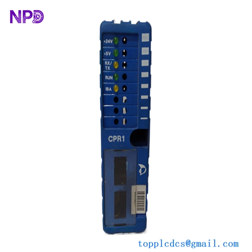
The Zenitel Marine SPA-500-V1 Terminal Board is a dedicated interface and distribution module designed for the SPA-V2 Public Address and General Alarm (PA/GA) rack systems. Operating as a centralized terminal interconnection hub, this board streamlines the wiring of loudspeaker loops, emergency audio inputs, and external alarm trigger lines. Its robust, marine-certified design ensures reliable signal routing and uninterrupted emergency broadcasting under harsh, high-vibration maritime conditions.
⚙️ Technical Specifications
- 📐 Dimensions: 165 mm x 115 mm x 45 mm
- ⚖️ Weight: 0.45 kg
- 🌍 Country of Origin: Norway
🚢 Applications
- Zenitel SPA-V2 Public Address and General Alarm systems
- Centralized marine entertainment and emergency override integration
- Main distribution frame routing inside shipboard sound system racks
- Interfacing external safety systems (MUTE commands, fire alarm signals)
🛠️ Usage Instructions
- Ensure the main PA/GA rack power is completely shut off before inserting or removing wire terminations from the board.
- Use the integrated testing points to measure line impedance and verify loudspeaker loop continuity during routine safety audits.
- Ensure all terminal screw clamps are properly tightened to prevent loose connections caused by continuous hull vibration.
- Do not apply external voltages to the discrete control inputs unless they match the specified system trigger thresholds.
🔧 Mechanical Installation Requirements
- Fixing Method: Mounted directly onto the internal chassis backplate or standard internal rack rails of the SPA-V2 amplifier enclosure using four pre-drilled M4 corner mounting holes.
- Space Clearance: Maintain a minimum clearance of 35 mm around the terminal blocks to facilitate clean wire routing, bending radiuses, and ease of technician access.
- Heat Dissipation: Passive convection cooling. Ensure it is positioned away from high-power amplifier transformer modules to keep ambient temperatures below 55°C.

🔌 Electrical Wiring Guide
- Terminal Definitions: * Terminals 1–4: 100V Loudspeaker Zone Output Loops
- Terminals 5–8: Emergency Alarm Override Control Inputs (Dry Contacts)
- Terminals 9–12: Auxiliary Audio Input Line Interfaces
- Terminals 13–14: 24V DC Internal Control Power Feed
- Chassis Ground: Dedicated terminal screw for shield termination
- Wire Gauge: Use minimum 0.75 mm² up to 1.5 mm² (18 to 16 AWG) twisted, multi-core shielded marine cables for audio lines, and up to 2.5 mm² (14 AWG) for power feeds.
- Grounding Norms: Connect the cable shields directly to the chassis ground terminal on the board, ensuring the shield is grounded at only one end to eliminate potential ground loops and hum noise.
📡 Communication Configuration
- IP Address: Not applicable. This model is a hardware termination interface and does not feature an integrated IP/Ethernet network layer.
- Station ID: Hardwired address routing; zoning configuration is managed physically via internal jumper links or centrally through the main rack’s control processor.
- Baud Rate: Not applicable. Transfers discrete analog audio and binary control triggers via low-voltage signaling paths instead of serial data protocols.
❓ Frequently Asked Questions (Q&A)
- Q: Why is there an audible hum coming from the connected loudspeakers?
- A: This is often caused by an ungrounded or improperly grounded cable shield. Ensure the audio line shields are connected securely to the board’s designated ground point.
- Q: Can this terminal board handle high-power speaker lines directly?
- A: Yes, it is rated for standard marine 100V constant-voltage audio distribution networks, up to the maximum total current limit specified for the SPA system channel.
- Q: What should I check if a specific loudspeaker zone fails to broadcast?
- A: Check the corresponding fuse on the main rack card, inspect the field wiring connected to that specific terminal block zone, and measure the loop impedance to ensure there is no short circuit.