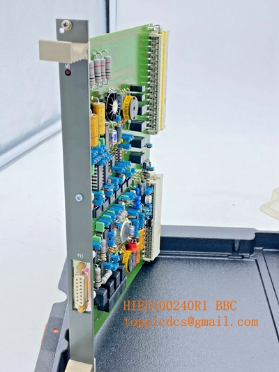
Description
- Model: ECPSR086370-001
- Brand: ABB (Switzerland/Sweden)
- Series: Power Supply / Excitation Control
- Core Function: DC Power Regulation and Signal Conditioning
- Type: Power Supply Module
- Key Specs: Multi-rail DC output, integrated thermal monitoring, high-voltage isolation
- Input Voltage: Typically 110/220 V AC or DC (System dependent)
- Output Rails: Provides regulated +/- 15 V DC, +5 V DC, and +24 V DC to control electronics
- Thermal Management: Integrated heat sink for passive cooling
- Protection: Over-voltage (OVP) and short-circuit protection (SCP)
- Isolation: High galvanic isolation between input and output stages
- Connectivity: Multi-pin edge connectors or heavy-duty terminal headers
- Standard Compliance: IEC 60255 or equivalent industrial power standards
- Weight: Approx. 1.2 kg
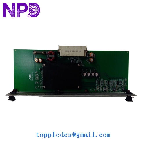
ABB ECPSR086370-001
Installation & Configuration Guide
Phase 1: Pre-Installation (Preparation: 10 minutes)
⚠️ Safety First: Excitation systems deal with high-energy DC fields.
- Ensure the generator is de-excited and the breaker is locked out.
- Discharge all high-voltage capacitors according to ABB’s safety manual.
- Verify the input power source is disconnected using a Fluke 115 or equivalent multimeter.
Phase 2: Removal (Step-by-Step)
- Mark Connections: Use a fine-tip marker to label any small gauge sensing wires.
- Loosen Fasteners: Use a Pozi-drive or Phillips screwdriver (PH2) to remove the module’s retaining screws.
- Extraction: Pull the module straight out to avoid damaging the edge connectors or backplane pins.
- Visual Check: Inspect the backplane for any signs of arcing or carbon deposits before installing the new unit.
Phase 3: Installation & Power-On
- Static Shielding: Remove the ECPSR086370-001 from its anti-static bag only when ready to insert.
- Alignment: Align the module with the guide rails. Slide it in until the connectors seat firmly.
- Secure: Re-tighten the retaining screws to ensure a good chassis ground.
- Voltage Verification:
- Power up the control rack.
- Measure the test points on the front of the module (if accessible) to verify the +5V and +/- 15V rails are within 2% tolerance.
- System Logic: Check the Unitrol control panel for any “Power Supply Fault” or “Undervoltage” alarms.
ABB ECPSR086370-001
Customer Cases & Industry Applications
Case 1: Hydroelectric Plant Voltage Instability A hydroelectric facility in Norway experienced fluctuating excitation voltage, causing the generator to hunt for reactive power. Troubleshooting revealed that the aging capacitors on their original ECPSR086370-001 were failing. Because we provided a New Surplus unit, the plant avoided a three-month wait for a custom-ordered modern replacement, restoring grid stability in under 48 hours.
Case 2: Emergency Response for a Paper Mill A large paper mill’s captive power plant suffered a power supply failure in the excitation cabinet. Every hour of downtime cost the mill $25,000 in lost production. We dispatched an ECPSR086370-001 via “next flight out” service. The part arrived, was installed by the on-site electrical team, and the mill was back at full capacity by the following morning.
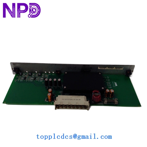
ABB ECPSR086370-001
Frequently Asked Questions (FAQ)
Q: Is this a direct replacement for older 086370 versions? A: Yes. The “-001” suffix usually denotes a specific revision level that is backward compatible with the base ECPSR086370 series. However, always check your technical manual for specific output current requirements.
Q: Why not just buy a used module for half the price? A: Power supply modules contain electrolytic capacitors that have a finite lifespan. A used module may already have 50,000 hours of heat exposure. In my experience, buying “used” power electronics is a gamble that usually ends in another failure within six months. New Surplus ensures you are starting with zero-hour components.
Q: Can you provide a test report for this specific serial number? A: Absolutely. We perform a full load test on every ECPSR086370-001 before it leaves our facility. This includes checking the ripple voltage on the DC rails and a 24-hour burn-in to ensure no infant mortality of the components. We can send photos of the test setup upon request.
Q: Does this require any software programming? A: No. This is a hardware power and regulation module. Once the physical jumpers (if any) are set to match your original board, it is a “Plug-and-Play” component. The system’s logic resides in the main controller, not this power supply.