Description
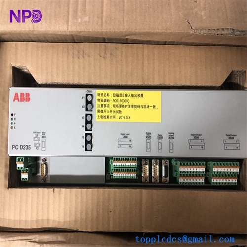
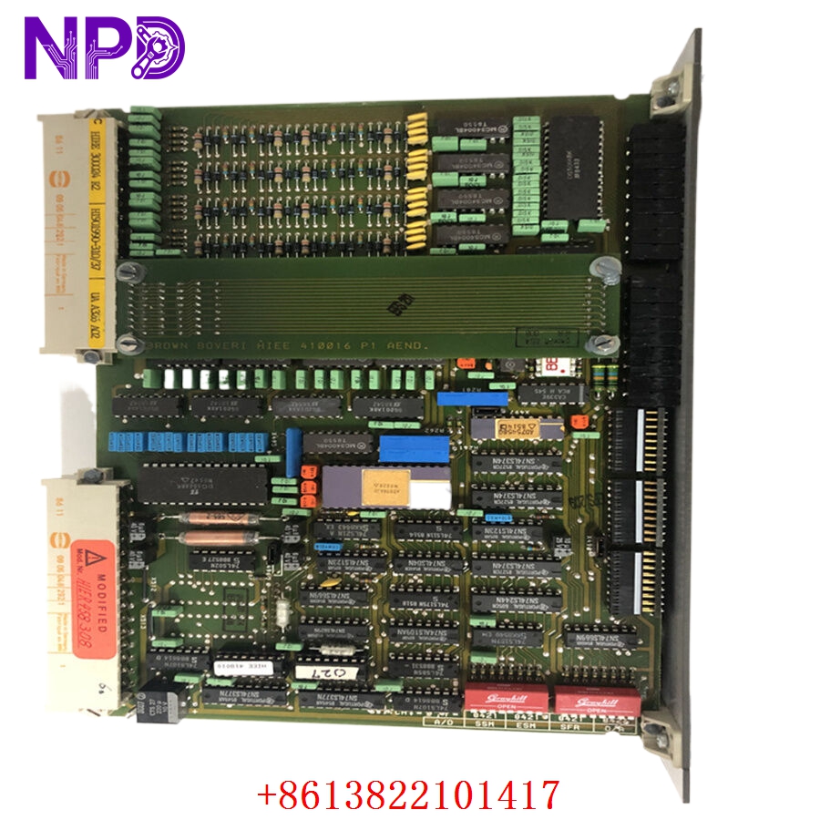
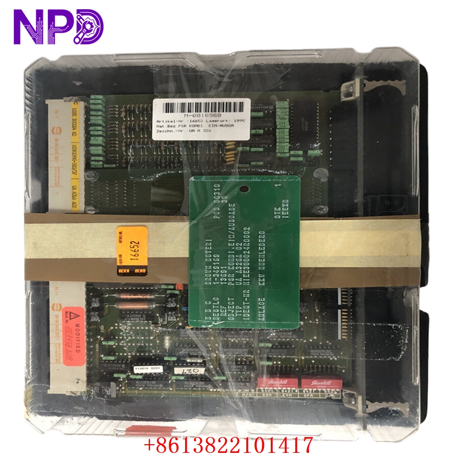
- Model: ABB UAA326A02
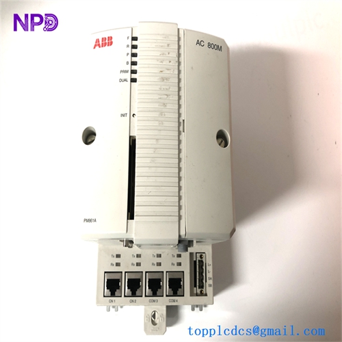
- Brand: ABB
- Series: Legacy Control System Series (often associated with older ABB master/process controller platforms)
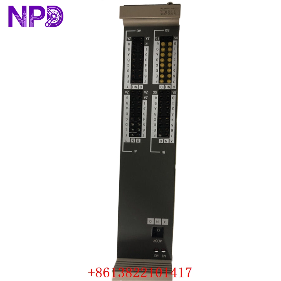
- Core Function: Converts analog signals (voltage or current) from field sensors into digital values for the PLC/DCS controller.
- Product Type: Analog Input Module
- Key Specs: Multi-channel analog acquisition, high-precision signal conversion, industrial isolation
- Input Type: Configurable for voltage (0–10 V) or current (4–20 mA) loops
- Resolution: Standard process industry resolution (typically 12-bit to 16-bit)
- Channel Count: Multi-channel (consult specific sub-revision for exact count)
- Isolation: Galvanic isolation between field inputs and system backplane to prevent ground loops
- Conversion Time: Fast scan rates for real-time process monitoring
- Diagnostics: Module health and signal out-of-range monitoring
- Mounting: Rack-mounted module for standard ABB process control cabinets
GE UAA326A02
GE UAA326A02
GE UAA326A02
Application Scenarios & Engineering Pain Points
The UAA326A02 is used for monitoring critical process variables like pressure, temperature, flow, and level. The most common engineering challenge with these legacy modules is “Impedance Mismatching.” Modern transmitters have different output characteristics than the sensors designed when this module was first released. If the module input impedance doesn’t match the transmitter output, the signal will “droop,” causing significant errors in process readings that are difficult to calibrate out.
Typical Application Scenarios:
- Power Plant – Boiler Monitoring Acquires high-precision signals from thermocouples and pressure transmitters for combustion control.
- Chemical – Batch Reaction Monitors sensitive temperature probes to ensure the batch remains within the safety envelope.
- Water Treatment – Flow Management Tracks inflow and outflow rates from large electromagnetic flow meters.
Case Study: Calibration Drift Resolution An industrial plant reported that their temperature readings were consistently off by 2%. They suspected a faulty transmitter, but after swapping it, the error remained. Upon testing the UAA326A02 module, we discovered that the analog-to-digital (A/D) converter was suffering from thermal drift. We replaced the module with a factory-calibrated surplus unit, which immediately restored the accuracy of the loop.
Troubleshooting Quick Reference
Don’t panic if your PLC shows an “Input Error.” Most analog signal issues are physical layer problems, not module failures.
| Failure Symptom | Possible Cause | Quick Check Method | Recommended Action |
|---|---|---|---|
| “Bad PV” / Out-of-Range | Broken Field Wire | Measure loop current at terminal | Check wiring and transmitter power |
| Noisy/Jittery Data | Ground Loop | Check for shield-to-ground shorts | Isolate shield to single-point ground |
| Consistent Offset | Calibration Required | Compare terminal voltage vs. PLC | Perform software loop calibration |
| No Module Status | Backplane Power Fault | Check module LEDs / Rack power | Clean pins and reseat module |
Engineer’s Note: ❗ Crucial Advice: Always verify the signal type setting. Many analog modules allow you to select between current and voltage mode via internal jumpers or software. If you have an input wired for 4–20 mA but the module is configured for 0–10 V, you will likely damage the input shunt resistor on the module. Always double-check the jumper settings before connecting field wires.