Description
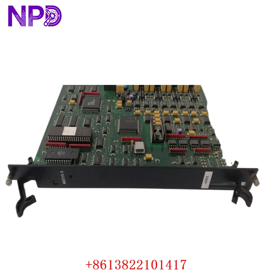
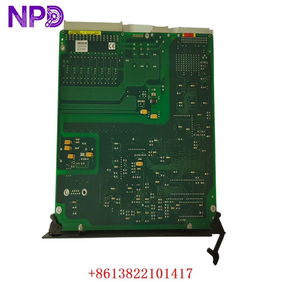
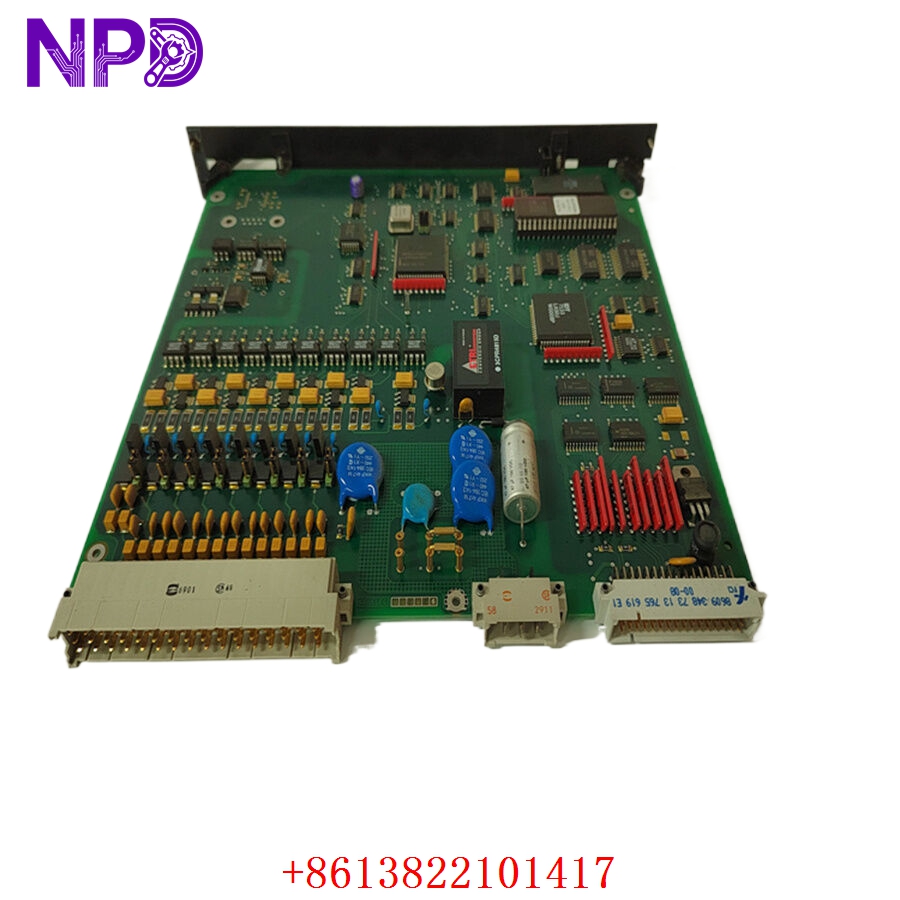
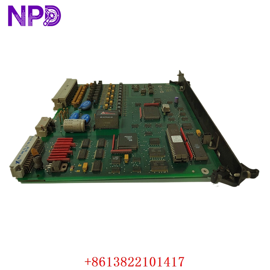
- Model: ALSTOM AH116-2 (Often listed under Alstom / Areva / Schneider Electric grid automation lineages)
- Brand: ALSTOM (France / Power Grid Division)
- Series: Alstom Automation / Protection Relay Subsystem Arrays
- Core Function: Combined discrete/analog input-output handling, managing hardware-to-logic interface routing inside high-voltage switchgear environments
- Product Type: I/O Interface Control Card / Substation Processing Board
- Key Specs: Multi-Channel Isolated Digital Inputs | Form C Rugged Interlock Relays | High Transient Surge Withstand Immunity
- Operating Operating Voltage: Dedicated nominal 24 V DC internal logic rail interface (supports wide-range battery station inputs depending on carrier rack options)
- Discrete Input Mapping: Multi-channel high-voltage optocoupler-isolated digital inputs (typically configured for 110 V DC or 220 V DC wetting voltages)
- Discrete Output Mapping: Integrated heavy-duty Form C (SPDT) electromechanical monitoring and trip relay paths
- Relay Contact Rating: Continuous 5 A at 250 V AC / 30 V DC inductive tracking limits
- Isolation Boundary rating: 2.5 kV AC galvanic isolation between field terminal points and inner processor bus structures
- Data Bus Configuration: Multi-pin high-density rear backplane edge connector for parallel processor interface integration
- Hardware Subversion: Revision -2 architecture, featuring upgraded surge suppression circuitry and improved thermal tracking profiles
- Environmental Conformity: Class G3 conformal coating for exposure resilience against particulate and chemical dust inside harsh switchyard control rooms
Application Scenarios & Engineering Pitfalls
The On-Site Reality
In high-voltage substations, power generation stations, and heavy industrial distribution networks, protection and control logic networks must operate without compromise. The ALSTOM AH116-2 serves as the vital physical gateway connecting your central control processors with external switchyard equipment, such as circuit breaker auxiliary switches, transformer alarms, and heavy motor contactors. When an I/O routing board like this breaks down due to an aging control component or a high-voltage surge, your main automation panel loses its ability to trip or track status profiles. Because the AH116-2 collection belongs to a legacy lifecycle category, finding an immediate, pre-tested replacement is the only way to avoid extended plant outages or dangerous unmonitored operational states.
Typical Deployment Scenarios
- Substation Automation – Circuit Breaker Control and Status Monitoring
Routes real-time open/close indicator states and trip coil supervision loops back to central bay controllers.
- Power Generation – Generator Excitation Panel Interlocking
Manages the digital safety interlocking sequences required to bring high-capacity utility generators safely onto the grid synchronized.
- Heavy Heavy Industry – Medium Voltage Switchgear Protection Systems
Interfaces external gas pressure (SF6) monitors, thermal sensors, and door interlocks directly into the plant’s automation system.
- Petrochemical Utilities – Coordinated Motor Control Center (MCC) Clusters
Passes remote start/stop commands and run-time trip feedback between isolated field units and the central DCS room.
Plant Survival Case Study: Substation Isolation Restored
- Background: A large-scale chemical processing plant operating its own co-generation plant suffered a localized substation failure when an ungrounded current transformer (CT) terminal block arced over inside an auxiliary control bay during a severe seasonal rainstorm.
- The Problem: The high-voltage transient punched through the protection lines, instantly damaging the input processing circuits on a legacy ALSTOM AH116-2 card managing status feedback for the primary substation breaker. The main panel logged a continuous “Breaker Discordance Fault” and locked down all automated grid-switching routines. The plant was forced to run on emergency manual procedures, risking a full production trip if load conditions shifted unexpectedly. The OEM listed the module as obsolete with no local warehouse stock available.
- The Solution: The automation engineer bypassed standard vendor delays by contacting our depot. We quickly located a clean, original-surplus AH116-2 board in our clean inventory reserve, ran it through our comprehensive isolation and relay cycling tests, and shipped it out via priority express transport within 4 hours.
- The Result: The replacement card arrived at the substation control room the next morning. The field crew completed the physical swap, verified backplane tracking integrity, and rebooted the bay controller. The breaker feedback link initialized instantly with zero errors, returning the substation to full automated operation and preventing a costly factory-wide shutdown.
Compatible Replacement Models
When working with vintage grid automation boards, verifying part numbers and revision suffixes prevents hardware layout conflicts during commissioning.
| Original Part Number | Alternative Model | Compatibility Level | Key Differences / Structural Variances | Required On-Site Modification Steps | Cost Variance |
| AH116-2 | AH116-1 | ⚠️ Software Compatible | Earlier revision platform. Contains older optocoupler components with lower transient surge ratings on the input tracks. | Check if field wiring requires external surge suppression filters if used in high-surge switchyard locations. | -15% |
| AH116-2 | AH116-2 Revision Core | ✅ Drop-in Replacement | Exact hardware build and engineering lineage match; features updated surge suppression components and identical backplane mapping. | Direct card-slot swap. Slide the new card into the rack rails and lock down the retaining fasteners. | Baseline Cost |
| AH116-2 | AI116-2 | ❌ Hardware Incompatible | Dedicated Analog Input board layout belonging to the same generation family but containing no discrete relay paths. | Completely different functionality, circuit layouts, and terminal assignments. Do not substitute. | +20% |
Quality Assurance & Testing Standard Operating Procedure
To eliminate performance concerns regarding legacy grid-automation modules or warehouse-aged components, every ALSTOM card undergoes a comprehensive verification process before shipment clearance.
[Inbound Traceability Log] ➔ [Optical Microscopic Audit] ➔ [High-Voltage Isolation Verification] ➔ [Automated I/O Loop Simulation] ➔ [ESD Secure Packing] 1. Inbound Traceability and Structural Screening
- Authenticity Profiling: Verifying the physical manufacturer nameplate, internal board traces, and manufacturing revision codes against Alstom’s grid automation production history.
- Chassis Assessment: Detailed optical tracking of the multi-pin rear edge connector, component solder joints, and mounting rails to ensure zero defects.
2. Optical Microscopic Solder Joint Audit
- Joint Analysis: High-magnification optical inspection of surface solder joints, searching for cold joints, micro-fractures, or oxidation built up over extended storage.
- Relay Component Check: Inspecting the sealed electromechanical relay housings to confirm there are no signs of thermal stress or casing discoloration.
3. Galvanic Isolation Circuit Verification
- Insulation Resistance Execution: Using a specialized digital insulation tester to apply 1,500 V AC across the field terminal input paths down to the internal backplane logic ground plane.
- Acceptance Threshold: The insulation barrier must measure above 10 MΩ to ensure absolute protection against field surges bridging into the primary processing rack components.
4. Automated I/O Loop Simulation
- The Testing Environment: The ALSTOM AH116-2 is mounted into a specialized testing array configured specifically to mimic active protection relay rack setups.
- Dynamic I/O Exercising: We apply nominal wetting voltages (110 / 220 V DC) across every single input channel while monitoring internal logic state changes.
- Relay Contact Stress Test: We cycle the output relays under full rated inductive loads for continuous loops to confirm crisp contact transition timing and verify zero contact pitting or leakage.
5. Final Quality Sign-Off and Secure ESD Packaging
- Tagging Protocol: The testing technician signs and applies a dated, serialized “QC Passed” label directly onto the anti-static enclosure layer.
- ESD Shielding: The card is sealed inside a heavy-duty, moisture-barrier anti-static bag packed with fresh desiccant.
- Shock Protection: Housed inside custom shock-absorbing foam layers within a heavy shipping box to eliminate any transportation risks.
Grid Control Module Field Troubleshooting Quick Reference
❗ SAFETY FIRST: High-voltage wetting lines (110 V DC to 250 V AC) may be active on the terminal blocks of this module even if the primary rack processor power is turned off. Always verify all field lines are completely de-energized using a certified voltmeter before handling the card or altering connections.
Q: The main bay controller displays a persistent “I/O Module Missing” or “Backplane Bus Error” targeting the slot containing the AH116-2 board.
A: Correlation: High. This problem usually indicates damaged edge connector pins on the rear of the board, or a failure of the card’s internal address decoding logic components.
- Safely isolate the power feed lines and pull the board from its slot rails.
- Inspect the multi-pin gold-plated rear edge connector under a bright light. Look for any bent, worn, or corroded contact pads.
- Clean the edge connector contacts using a high-purity, residue-free electrical contact cleaner. If the backplane lines are clean but the fault won’t clear upon reinsertion, the board’s internal address logic has failed. Swap it for a verified spare.
Q: External equipment status shifts physically, but the controller display shows no change and the input status LED on the AH116-2 front panel remains dead.
A: Correlation: High. The optocoupler isolation component for that specific input channel has likely blown due to a high-voltage surge or external wiring short circuit.
- Use a digital multimeter to measure the wetting voltage directly across the corresponding input terminal screws while the field device is closed. Verify the voltage matches your system’s target range (110 / 220 V DC).
- If correct wetting voltage is present right at the input terminals but the board’s internal status LED stays dark, the input channel processing circuit is dead.
- Honest technical truth: Do not attempt to modify these surface-mount components on-site. Move your wire connections to an unassigned spare channel if available in your program code, or replace the board.
Q: The logic system triggers a command to close a circuit breaker, but the physical relay on the AH116-2 clicks without passing power downstream to the trip coil.
A: Correlation: High (Contact pitting or wear). The internal electromechanical relay contacts on that channel have likely developed severe carbon pitting or welded open after years of switching high inductive currents.
- Isolate the external power line and disconnect the field wires from the target relay contacts.
- Use a digital multimeter set to resistance (ohms) to check contact continuity across the Form C terminals while forcing the output channel manually using your engineering tool.
- If the meter registers an infinite or highly unstable resistance loop while the relay coil is energized, the contact paths are worn out. Replace the entire interface board to restore dependable protection capabilities.
❗ Critical Installation Guidelines for On-Site Technicians
- Verify Your Wetting Voltage Selection: Before sliding the replacement card into service, verify that your field wiring wetting voltages match the hardware configuration of the new module. Connecting a high-voltage 220 V DC link to a board configured for low-voltage 24 V DC inputs will permanently damage the input optocouplers.
- Ensure Rigid Rail Alignment: When inserting the board into its slot space, ensure it tracks smoothly along both the top and bottom guide rails. Pushing the card in forcefully when it is misaligned can easily bend or break the high-density backplane pins on the rear connector block.
- Ground Cable Shields Properly: Ensure that all incoming field cables are routed with high-quality shielding. Connect the shield drain wire to the designated panel grounding bar at one end only to prevent ground loop currents from injecting noise into your low-voltage control signals.