Description
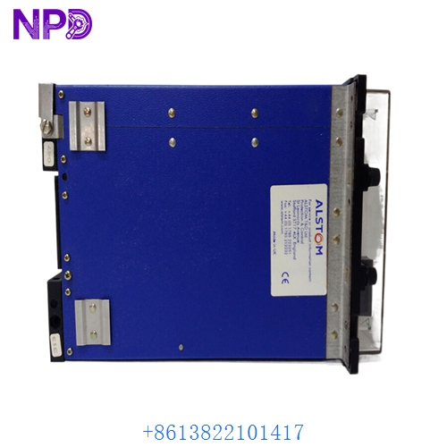
- Model: Alstom AS111-1 (Belongs to the Alspa CE2000 / CE3000 series platform)
- Brand: Alstom / GE Power Conversion (France)
- Series: ALSPA Distributed Control System (DCS) (Extensively found in gas/steam power plants, turbine speed regulations, and hydro-generation control networks)
- Core Function: Acts as an 8-channel analog output module interface translating digital processor instructions into standard current signals to drive valves, actuators, and indicators, Brand New Surplus condition
- Type: Analog Output I/O Module Card
- Key Specs: 8 Current Output Channels | 0-20 mA or 4-20 mA configurable range | High Galvanic Isolation from backplane
- Channel Density: 8 analog output channels referenced to a common 0 V return line
- Output Signal Ranges: Configurable for 0 to 20 mA or 4 to 20 mA industrial loops
- Process Operating Voltage: Designed for standard 24 V DC system process voltage distribution rails
- Overcurrent Protection:
- Main process voltage supply loop protected by integrated CTP (positive temperature coefficient) thermistor elements (Max trip current: 0.75 A at 20 °C)
- Individual channel-level isolation protection by localized CTP blocks (Max trip current: 0.3 A per channel)
- Galvanic Isolation Barrier: Optocoupler design separating digital control logic from external field loop wiring (Up to 1,500 V DC isolation)
- Resolution Matrix: 12-bit to 16-bit internal digital-to-analog processing range (module variant dependent)
- Status Indication Panel: Front-facing diagnostic LED indicators indicating Module Active (Run), Fault, and loop state tracking
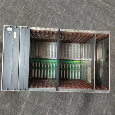
- Module Dimensions: Standard Eurocard board layout profile, matches ALSPA rack slot guide lanes
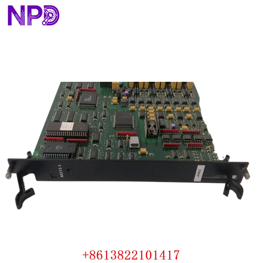
ALSTOM AS111-1
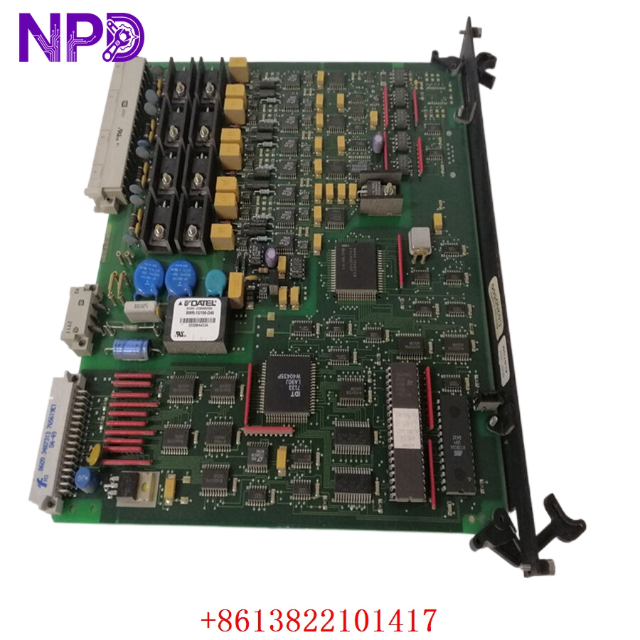
ALSTOM AS111-1
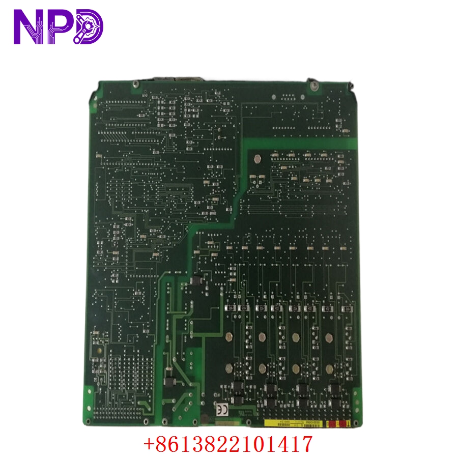
ALSTOM AS111-1
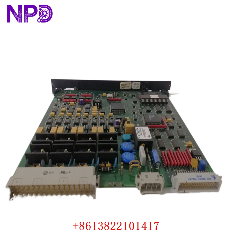
ALSTOM AS111-1
Part 4: Installation & Configuration Guide
Phase 1: Pre-Installation (Estimated Time: 20 minutes)
⚠️ Safety First:
- Contact the plant operations room to verify the target machinery loop (e.g., fuel control valve, hydraulic actuator, governor system) is placed into a secure manual bypass or physical maintenance lock state. Never extract an analog output card while the automatic closed-loop controller is driving live valves.
- Isolate the external 24 V DC process loop power supplies running to the terminal blocks of this slot.
- Apply standard Lockout/Tagout (LOTO) protocols at the power terminal breaker boxes.
- Wait a minimum of 3 minutes for the residual filter capacitors inside the local rack backplane to completely de-energize.
Tool Preparation:
- Static-dissipative grounding wrist guard and a clean, static-safe ESD workspace mat
- Flathead instrument precision screwdriver (2.5 mm blade)
- Phillips screwdriver for faceplate installation screws
- Fluke 115 Digital Multimeter
- Wire identifier labels, marking pen, and a high-resolution smartphone camera
Backup Procedures:
- Log into the ALSPA engineering terminal (e.g., Centralog or relevant software utility). Take a full snapshot and export log of the current I/O parameter maps, signal calibrations, and slot layouts configuration matching this specific sub-rack position.
Phase 2: Removal (Estimated Time: 10 minutes)
Steps:
- Verify with your multimeter that the 24 V DC field process voltage and terminal block points read 0 V.
- Unplug the front terminal block wiring connector strip from the AS111-1 card faceplate, using your reference camera to log layout alignments.
- Back out the upper and lower captive structural screws pinning the card’s front edge plate to the sub-rack rails.
- Pull the module’s extraction tabs straight outward evenly to back the board away from its parallel backplane connector pins.
- Slide the analog module card smoothly out along its guide tracks and immediately pack it inside an ESD-shielded storage bag.
⚠️ Key Notes:
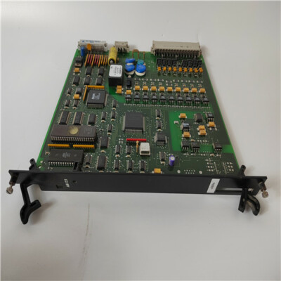
- These modules are available in distinct board color variants (such as historical black and newer blue cards). Ensure you verify that the new card form factor matches your base termination socket styles (UT129 / UT150 / UT156 matrix sub-assemblies).
Phase 3: Installation (Estimated Time: 15 minutes)
Steps:
- ESD Protection: Connect your grounding wrist strap to a verified chassis ground point before unpacking the new surplus AS111-1 PCB card.
- Hardware Layer Verification: Look closely at the circuit board layer. Check and replicate any physical hardware jumpers or DIP switches from your old decommissioned card to the new one. These configure whether the channels run on a 0-20 mA vs 4-20 mA profile, and establish slot logic.
- Insert Board: Align the upper and lower board edges cleanly inside the designated card guide tracking lanes of the rack slot.
- Seat Connectors: Slide the card smoothly inward until it contacts the backplane. Press firmly until the rear multi-pin connector seats completely into the backplane socket assembly with zero mechanical play.
- Secure Frame: Tighten the top and bottom panel screws to lock the card to the rack frame, then re-attach the wire termination connector strip.
Self-Check Checklist:
- [ ] Internal signal logic jumpers and hardware range scales match the original module settings exactly
- [ ] Card is pushed completely into the backplane socket without uneven alignment gaps
- [ ] Faceplate mounting screws are hand-tightened down flush with the rack rails
- [ ] Wiring block terminal connection is clicked securely into position with no loose wire braids
Phase 4: Power-On & Diagnostic Loop Verification (Estimated Time: 25 minutes)
Pre-Power Checks:
- Probe the isolated terminal lines with your multimeter to check for any low-resistance short circuits to ground across the 24 V DC process loops.
Power-On Steps:
- Remove LOTO tags and flip the auxiliary process loop control power breaker back to ON.
- Observe Initial LED Status: The front panel RUN (Green) indicator light should turn solid. If the red FAULT light illuminates or stays flashing, cut power to verify hardware settings or slot matching via the software interface.
- Connect your engineering terminal software and monitor the live I/O diagnostics tree to confirm the master controller reads the card as healthy and matching its slot profile.
- Signal Loop Verification: Force a fixed signal command (e.g., 50% / 12 mA output) from the engineering screen for Channel 1. Connect your multimeter in series on the field loop terminal and verify the actual current readouts match the engineering command exactly.
- Repeat this loop step check for all active channels across the board.
- Once stable operation is recorded across a 15-minute window, safely return the control loops back to operational status. Record the new serial number in your plant log book.
Part 5: Customer Cases & Industry Applications
Case 1: Restoring Valve Control on a Steam Turbine Governor Loop
Situation: A thermal power generation facility in Southern Europe relies on an Alstom ALSPA control platform to manage its main steam turbine parameters. During a grid load shift, an internal component fault shorted out an output channel on the primary analog card, part number AS111-1, causing the steam governor valve positioner to fail safe and triggering an immediate automated plant trip.
Task: The power block was forced into an unscheduled outage, costing the station significant generation revenue for every hour the control loops remained offline. Because this generation of ALSPA components had entered obsolete status, local suppliers quoted long lead times to source or repair matching hardware from overseas depots.
Action: The plant’s instrumentation engineer contacted our logistics warehouse. We verified an un-used surplus AS111-1 card within our climate-controlled stock. Our laboratory technicians initialized the module on our ALSPA test bench, confirmed clean signal feedback loops across all 8 analog channels, and dispatched the item via priority overnight air courier.
Result:
- Uptime Restored: The package reached the plant site within 16 hours of the initial fault. The maintenance technicians replicated the jumper configuration and completed installation within 20 minutes.
- Stable Valve Operation: On power-up, the module passed its initialization checks immediately. The steam governor valve position response returned to stable limits, allowing the station to re-sync with the power grid ahead of schedule.
- Customer Voice: “Sourcing an authentic, un-used legacy board for our ALSPA rack on short notice saved our turnaround window. The module was an exact match, dropped in cleanly, and cleared our safety block instantly.”
Case 2: Strategic Spares Backup for a District Hydropower Station
Situation: A remote hydro plant utilizes legacy ALSPA CE2000 controller racks to manage hydraulic deflector blocks. The positioning loops rely on multiple AS111-1 cards to send constant 4-20 mA current loops to hydraulic servo units.
Task: Understanding that a sudden failure of an aging analog card would lock the deflectors—potentially forcing an emergency water discharge or mechanical overload—the reliability group wanted to secure reliable backup inventory before global market supplies disappeared. Sourcing worn, refurbished alternatives was rejected due to strict facility reliability standards.
Action: The procurement team contacted us to secure an authentic, un-used component. We supplied a matching AS111-1 module inside its original, sealed anti-static factory packaging, complete with clean manufacturing numbers, allowing the facility to confirm the pristine condition of the board before adding it to their safety stock.
Result:
- Long-Term Protection: This strategic purchase provided the plant with a reliable, plug-and-play backup component, ensuring they can keep their legacy control systems running smoothly for years to come without requiring an expensive and un-planned full-system upgrade.
Part 6: Frequently Asked Questions (FAQ)
Q1: What is the exact difference between the AS111-1 and newer AS111-2 module configurations?
A: While both are 8-channel analog output modules within the ALSPA architecture, they are designed for different field voltage applications:
- The AS111-1 is optimized primarily for standard legacy field layouts matching original system specifications.
- The AS111-2 includes modified overcurrent threshold limits and internal trace designs optimized specifically for standard 24 V DC process loops to run cooler under continuous max load.
Both cards share identical backplane interfaces, but you must verify that internal jumper options are matched when substituting variants.
Q2: Why do these modules come in different board colors, and are they fully compatible?
A: Yes, Alstom manufactured these modules in both black and blue circuit board color variants over their lifecycle. The different colors simply represent different production eras and material baselines. Both colors share the exact same technical configuration designator (C0200550 level prints) and are fully plug-and-play compatible with your existing UT129, UT150, or UT156 rack terminal socket slots.
Q3: Can I hot-swap the AS111-1 module while the sub-rack is powered and active?
A: No, you should never hot-swap this analog output card while the control power is active. Pulling an I/O card while the backplane data bus is energized can cause electrical arcing across the connection pins.
This can corrupt data on adjacent communication lines, damage the internal processing chips, or cause connected safety and I/O modules to enter an unpredictable fault state. Always shut off auxiliary power to the rack chassis before pulling or installing a processor.
Q4: Why buy a New Surplus Alstom module instead of a cheaper refurbished option online?
A: Refurbished analog cards are typically salvaged from old, decommissioned industrial plants. Third-party repair shops often just clean the outer terminals or replace blown input fuses, leaving old internal digital-to-analog converters (DACs) and isolation optocouplers intact. These old components are prone to failing unexpectedly when subjected to continuous data transmission.
Our New Surplus units are authentic, un-used modules stored in climate-controlled warehouses. They provide factory-original component lifespans and come backed by a full 12-month warranty, ensuring reliable protection for your machinery without the risks of refurbished hardware.
Q5: How do you verify the current output loop precision before shipping?
A: Every AS111-1 board goes through a rigorous quality check on our specialized ALSPA test benches before leaving our facility. We slide the card into a live matching chassis sub-rack, load calibration commands via our engineering station, and map the outputs against a calibrated digital ammeter across full scale (0 mA, 4 mA, 12 mA, 20 mA).